Part 64: Secret Project - Part 2
Part 3 - Harmony Sitar and Chorus Piano (HARMONY2)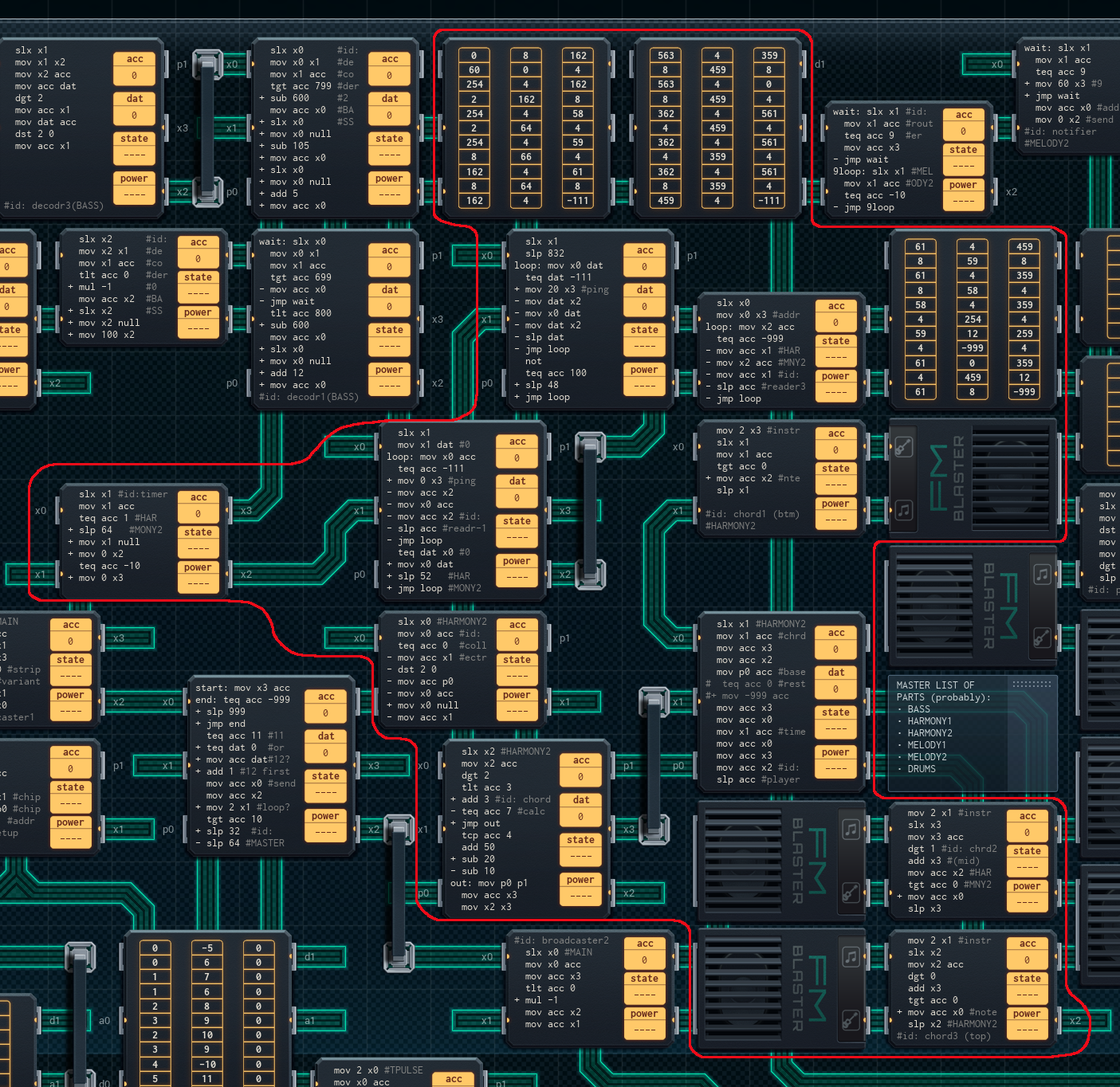
Most of the parts past this point are easier to understand and generally all-round simpler. This part is one example - it plays during where the sitar melody was in the original song, as well as doubling up on chords during the chorus. It uses an encoding scheme, like the harmony guitar chords, where each note is stored in 2 ROM chip cells. However, the Score ROM chips here only store single notes, instead of timed patterns of them. This simplifies the part’s construction immensely.
Harmony Sitar/Piano Chord Encoding
Like HARMONY1, this part uses 2 score cells per note. The encoding scheme is a bit different in this part.
The first cell details everything about a single chord - both the pitch of its base note and the chord to use. The leftmost digit of the number in the cell tells what chord to use. The other two digits of the first cell tell the pitch of the bottom note of the chord. If the first cell is entirely 0, however, this indicates a rest instead of a note.
The second cell lists the length of time the chord lasts. A ‘2’ is a sixteenth note (2 time units), a ‘4’ is an eighth note (4 time units), an ‘8’ is a quarter note (8 time units), and so on.
(The table of chords is listed below, under 6. Chord Calculator).
There are two single-cell control codes, as well: “-111” indicates that there’s no more room on the score chip, and the reader should switch to the next one. “-999” indicates the end of a section.
How it All Works
1. Receiver
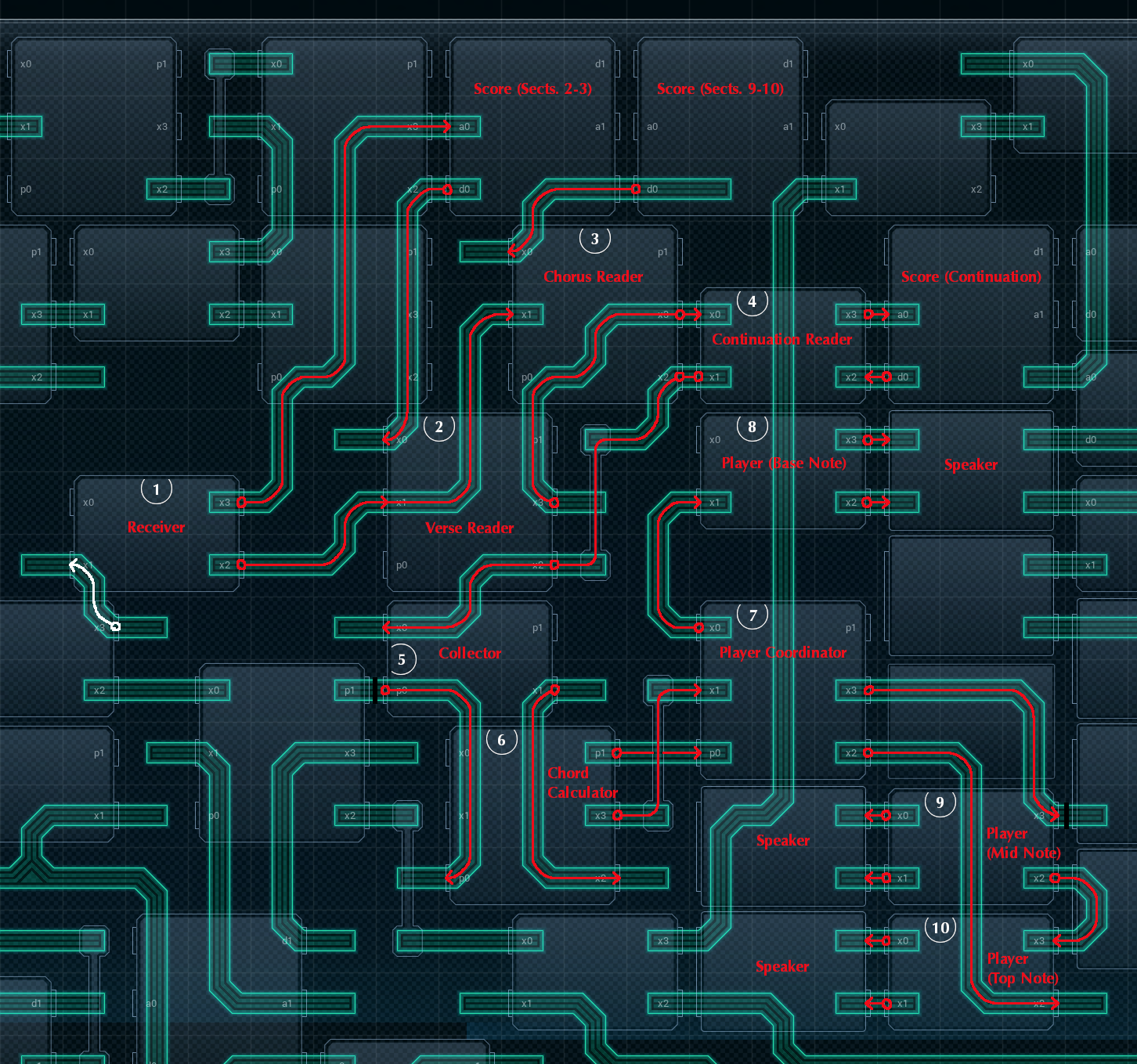
Most Receiver MCs have a big job: notifying the relevant MCs when it’s their turn. However, this part of the device only plays during two sections of the piece, so this Receiver's design is a little different. This Receiver will notify the Verse and Chorus Readers at the start of the second ‘1’ section (right before the sitar melody kicks in) - and it’ll reset the address pointer of the top left Score ROM chip at the end of the chorus (this is so that the Verse Reader can work properly once the song repeats).
Aside from the above duties, this Receiver throws out all other messages from the conductor. Life is relaxed in HARMONY2 town!
2. Verse Reader
The Verse Reader gets notified by the Receiver when it’s time to start playing. It’ll immediately start reading pairs of values from the attached ROM chip (Score, Sections 2-3; the left ROM chip in the top row), and sending them to the Collector, directly below.
(This part of the device uses a ‘push’ timing architecture only - signals only flow from the conductor, to the Readers, to the Players, to the speakers - never in the other direction. The Verse Reader will use the timing values it reads to know how long to wait before reading the next pair of values.)
As it turns out, the score for the sitar section is too large for a single ROM chip to contain it. So, when the Verse Reader reads the control code ‘-111’, it pings the Continuation Reader (see 4. Continuation Reader, below), which carries on where the Verse Reader leaves off. The Verse Reader will wait for 52 time units (1 and 5/8 measures) for the Continuation Reader to finish; then, it repeats the sitar part once from the beginning.
3. Chorus Reader
The Chorus Reader gets notified by the Receiver from the same pulse that notifies the Verse Reader. There’s one major difference: the Chorus Reader then waits 832 time units (26 measures), and then starts reading. Effectively, the starting wait acts as a timer to ensure the chorus chords flow at just the right time. The Chorus Reader reads from the “Score, Sections 9-10” ROM chip, in the top center.
Like the Verse Reader, the Chorus Reader sends the data it reads to the Collector MC. The score for the chorus section is also too large for a single ROM chip; on reading the control code ‘-111’, the Chorus Reader pings the Continuation Reader to pick up where it left off.
As the chorus repeats once, the Chorus Reader will wait 48 time units (1 and 1/2 measures) for the Continuation Reader, then read its section of the Score from the top again.
4. Continuation Reader
The Continuation Reader is responsible for reading the back half of the score segments for both the sitar melody and the chords used for the chorus. Both back parts are stored in the Score chip attached to the Reader, labeled “Score (Continuation)”.
The Continuation Reader knows where to start reading because: when one of the other Readers pings it, the ping contains the address of the cell in the ROM chip to start reading from. The Verse Reader pings with cell 0; the Chorus Reader pings with cell 20. This way, both segment parts can coexist on the same ROM chip.
Like all other Readers for this part, the Continuation Reader sends the data it reads to the Collector. If it reads a ‘-999’, it considers its job done, and waits to be pinged again.
5. Collector
The Collector receives the two-cell score data from the Readers, and sends it to the Chord Calculator just below. If the data it receives has a first-cell value of ‘0’ (signifying a rest), it throws it out and waits for the next data instead (no need to wake up the Players to play nothing).
When the Collector does send the data to the Chord Calculator, it splits it into two: the pitch data gets sent over its p0, while the chord and timing data get sent over XBus. This is so that the Chord Calculator can act as a pass-through for the pitch data.
6. Chord Calculator
The Chord Calculator’s job is to take the first digit from the received chord value, then calculate the actual chord number. Digits from 0-2 indicate a two-note chord, and digits from 3-5 indicate a three-note chord.
0 = 03 (minor third)
1 = 04 (major third)
2 = 05 (fourth)
3 = 43 (major chord)
4 = 54 (major chord, second inversion)
5 = 75 (octave with a 5th in the middle)
The ‘sitar’ verse section only uses two-note chords, while the chorus section uses almost entirely 3-note chords. Once the Calculator has the final chord value, it outputs it and the timing value (copied from the Collector) over its x3 line, to the Player Coordinator.
The Chord Calculator also takes the pitch value from its p0, and copies it over to its p1. This is only because I wasn’t able to run a simple I/O line from the Collector to the Player Coordinator.
7. Player Coordinator
Like the harmony guitar part’s Player Coordinator, this Player Coordinator is here to deal with the issue that there are three separate Player MCs - one for each note of the chords this part plays. This Player Coordinator’s script is almost the same as the harmony guitar part’s, too— it sends the chord value from the Chord Calculator to the Mid Note and Top Note players, the pitch value (received on its p0) to the Bass Note and Mid Note Players, and the timing value to all three.
8-10. Players (Base, Mid, and Top Note)
The Player MCs use the same pattern as the Players for the harmony guitar chords part. The Base Note Player plays the pitch value for the set amount of time. The Mid Note Player takes the pitch value, adds the left digit of the two-digit chord value, and plays that. It also sends its modified pitch value to the Top Note Player, which adds the right digit of the two-digit chord value - and then plays that. All three Players wait for the period given by the timing value, then stop their note.
There are a few quirks of these Players that don’t apply to the harmony guitar versions, though. First off, all three players still play if it’s a two-note chord. Due to the way the Chord Calculator is set up, the Base and Mid Note players will both play the lower note of the chord, and the Top Note Player will play the upper note.
On top of that, there’s also a slight design flaw. These Players check if the received pitch value is greater than 0, and will only play if that’s the case (so that the part is silence if the score indicates a rest). However, due to a line of code in the Collector that checks for a rest earlier (and only sends data Playerward if it’s an actual note), these tests will always pass - they’re redundant!
Yeah. I never got around to fixing it. I could save a few lines of code this way, but the device is done and that’s what matters.
The speakers for this part use instrument #2, “Tines”.
Total cost for this part: 1x MC4000 (¥3) + 5x MC4000X (¥15) + 4x MC6000 (¥20) + 3x 200P-33 (¥12) + 3x FM/iX (¥15) = ¥65.
Part 4 - Melody Vocals (MELODY1)
The main melody line parts are a lot more straightforward than the previous sections of the piece. Each note is stored in one cell of a ROM chip. There’s no chords to deal with. The Readers send directly to the Players. All in all, it’s a lot less of a headache!
Vocals Note Encoding
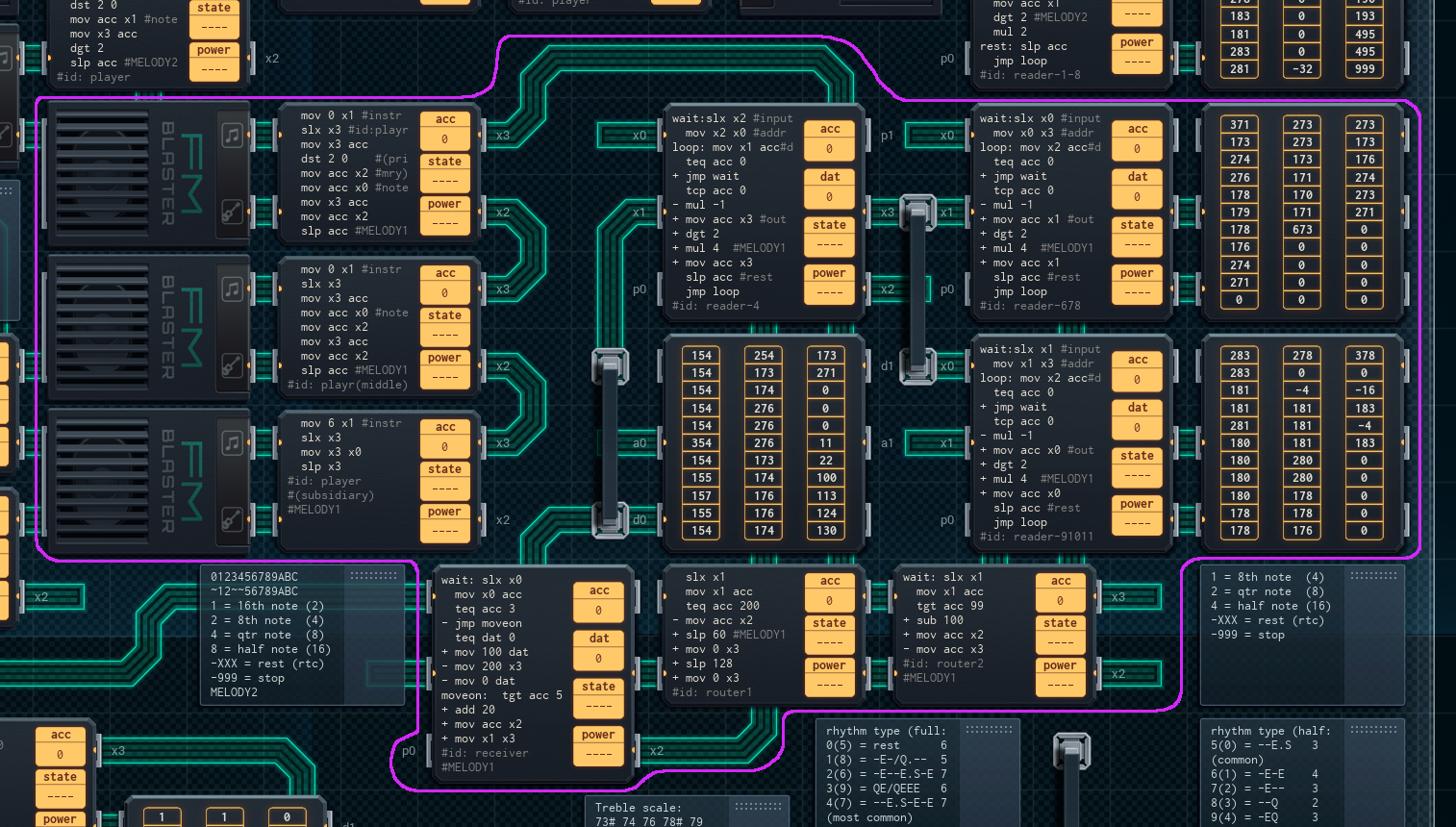
Each note in the vocals is stored in one ROM chip cell. For positive numbers (indicating notes), the leftmost digit of the cell indicates the node length (1 = eighth note, 2 = quarter note, 3 = dotted quarter note [1.5x a normal quarter note], 6 = dotted half note [1.5x time a normal half note]), and the other two digits are the pitch of the note. A negative number indicates a rest for that many time units, while a 0 marks the end of a section (which will cause the active Reader to stop reading).
How it All Works
1. Receiver and Address Getter
The Receiver’s job is to listen for cues from the conductor, as always - and then, tell the rest of the part what ROM chips to read from. However, while this Receiver uses a score address table, it’s not in a separate memory chip. Instead, this part’s Receiver uses free space at the end of the Score ROM chip for Section 4 (just up and to the right of it) as its address table instead! The Receiver will get the right address (as long as the section cued is #6 or higher), and send it along to the Routers (see 2-3. Routers, below).
This Receiver also has one hardcoded address in it, as well - this is because the Reader that reads from the Section 4 Score ROM chip has to start a few beats before the conductor cues in section 4. This is so that it can do a few notes that are part of a pick-up bar to section 4. As such, the Receiver waits until the second cue for section 3, then sends the hardcoded address ‘200’ on to Router #1 instead.
2-3. Routers #1 and #2
The address the Receiver digs up gets sent to Router #1 first. If it’s a ‘200’, signaling that Reader #1 is due for its cue, Router #1 will wait 60 time units (1 7/8 measures), then cue Reader #1. It’ll cue Reader #1 again 4 more measures after that, because its section repeats, but the cue from the Router does not.
If the address the Receiver sends over is not a ‘200’, Router #1 will pass it to Router #2. An address more than 100 will be sent to Reader #3 after its first digit is removed, while an address less than 100 will be sent to Reader #2.
4-6. Readers #1-#3
All three Readers have the exact same code (except for different pin numbers to accommodate different wiring schemes). Each Reader gets input from one of the two Routers, and when triggered, they move to the indicated starting address of their attached Score ROM chip, reading values from there until they hit a ‘0’. Like the harmony sitar and chorus chord Readers, these Readers keep track of the time of each note by themselves.
The notes each Reader reads are sent to the top Primary Player on the left. Each note gets turned into two sent values: the first is unchanged from the read value, and is used for the pitch. The second is the timing value (leftmost digit) extracted from the read value, which is used for the timing.
7-9. Players (Primary and Secondary)
Unlike the harmony guitar part or the harmony sitar/chorus part, this part of the device does not need to do chords. However, there’s three Players anyway. This is so that the melody part doesn’t get drowned out by the harmony parts - both have the same number of speakers at their disposal. Each Player will send the received note and timing information to the next Player in line, if there is one, before cueing their attached speaker for the amount of time the note runs.
The speakers for this part use instruments #0, “Harpsiclav”, and #6, “Reso Strings”. The difference between a Primary and Secondary player is that the Primary Players use Harpsiclav, and the Secondary Player uses Reso Strings. This makes a nice blended sound.
Total cost for this part: 5x MC4000X (¥15) + 4x MC6000 (¥20) + 3x 200P-33 (¥12) + 3x FM/iX (¥15) = ¥62.
Part 5 - Melody Strings (MELODY2)
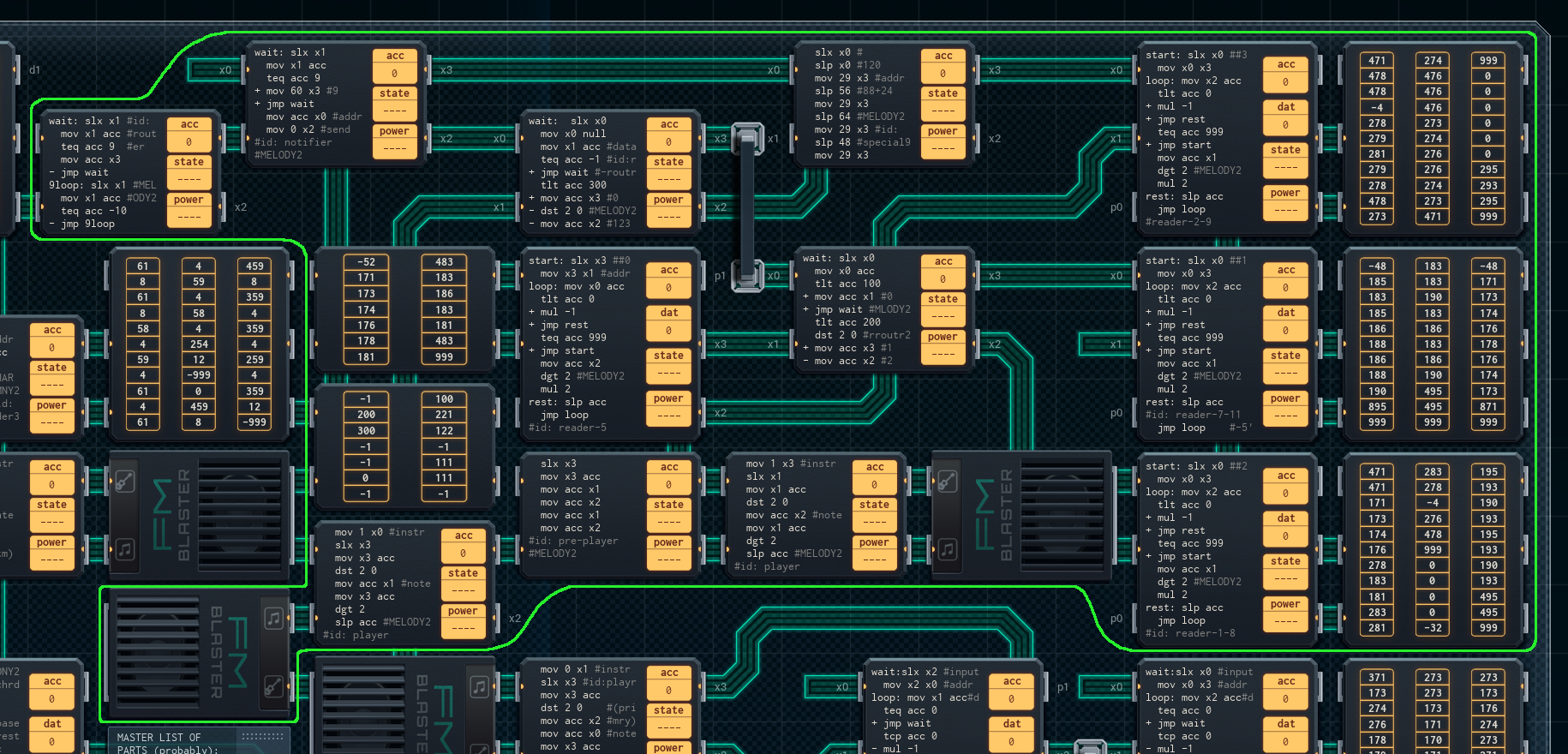
The melody strings part is very similar to the melody vocals part. It is slightly more complex, however - the biggest complication comes with the fact that the melody strings are playing more frequently (often for short ‘stings’), so the part needs more ‘Score’ ROM chips to store all the data. This part has the most Score ROM chips of any part of the device, at 4 distinct chips!
Strings Note Encoding
Like the vocals, each note in the strings is stored in one ROM chip cell. Positive numbers (other than 999) indicate notes. The leftmost digit of a cell with a note value indicates the note length (1 = sixteenth note, 2 = eighth note, 4 = quarter note, 8 = half note), while the other two digits indicate the pitch of the note. Negative numbers indicate to rest for that many time units (32 time units to a full measure). A ‘999’ marks the end of a section - once a Reader reads this value, it will stop.
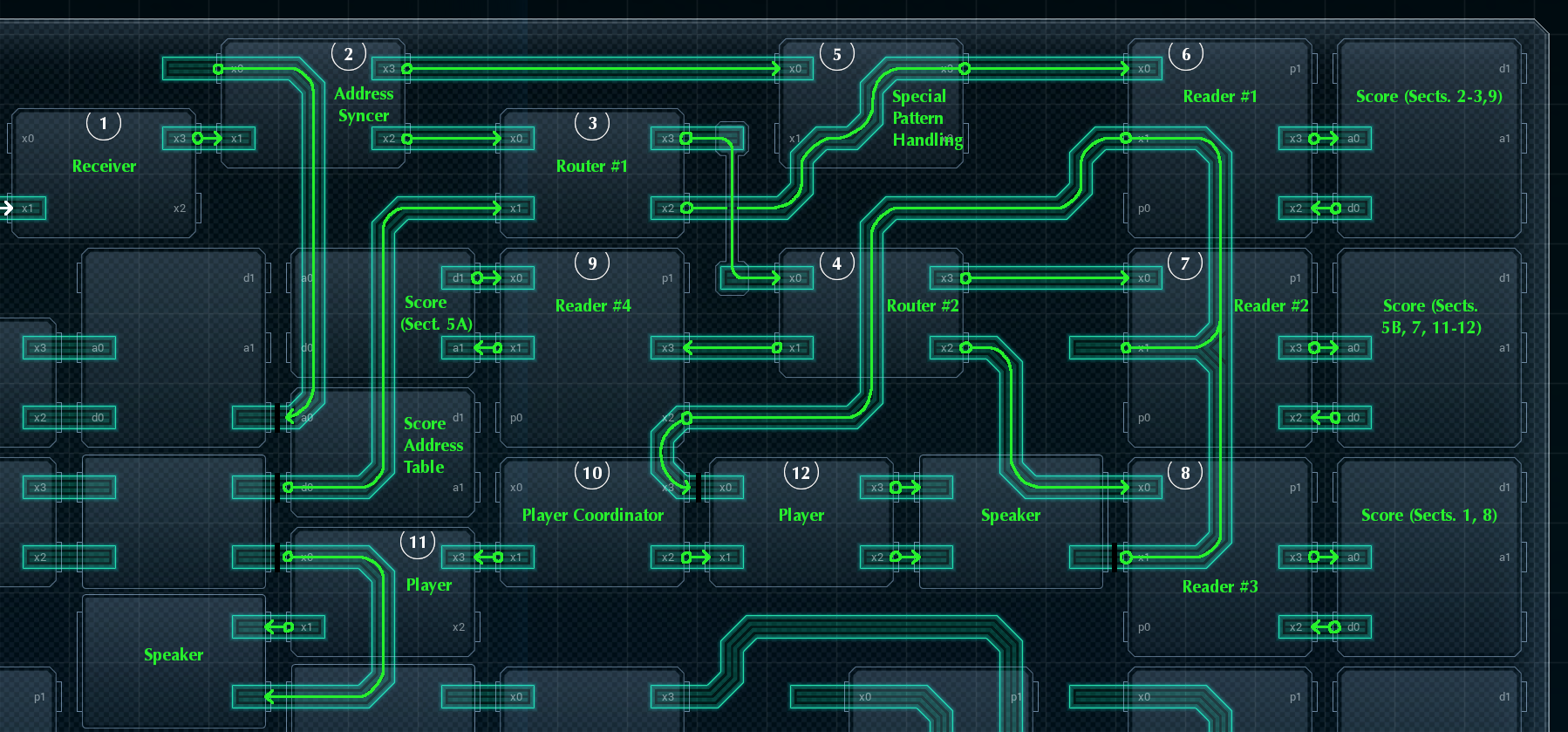
How it All Works
1. Receiver
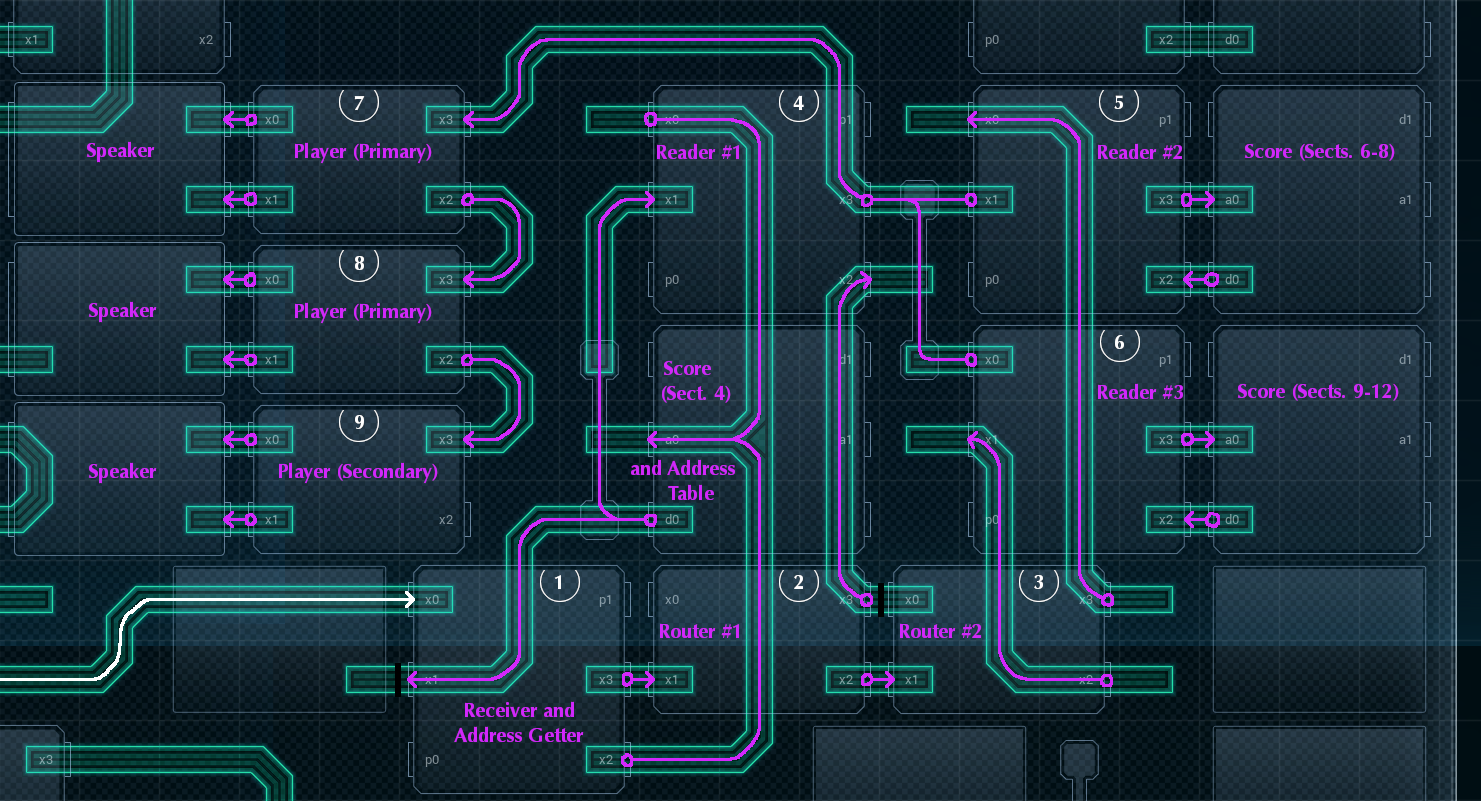
The Receiver’s job is simple: it gets the cues from the conductor, and passes them on to the Address Syncer, just to its right. However, there is one quirk: if the Receiver gets a cue for section 9 (the start of the chorus), the Receiver will discard all further cues until the chorus is over. This is because the chorus’s timing is handled separately by the Special Pattern Handling MC, down the line (see 5. Special Pattern Handling, below).
2. Address Syncer
The Address Syncer gets the most recent cue from the Receiver. If it’s a ‘9’, signaling the start of the chorus, it immediately pings the Special Pattern Handling MC. Otherwise, it uses the cue to set the address pointer of the Score Address Table ROM chip, which is tucked beneath the ROM chip for the Score, section 5A.
Fun fact: if the cue the Receiver passes on is for the variant section -5, the Syncer uses it to set the address of the Score Address Table ROM chip anyway! The ROM chips used will use modulo arithmetic to turn any out-of-range address into a number between 0 and 13 (or 0 and 32 for big ROM chips), so “-5” points to cell 9 (normally unused, because the chorus is handled separately).
Once the Address Syncer has set the address pointer of the Score Address Table, it notifies Router #1 that it’s ready to go. (Like the melody vocals, this part uses an entirely ‘push’-based timing model, so no fancy timing tricks need to happen at any point along the line.)
3-4. Routers #1 and #2
The Routers, collectively, ensure that the address of where in the Score to start reading gets properly delivered to the Reader equipped to handle it. (See 6-9. Readers, below.)
Router #1 reads the address from the Score Address Table ROM chip (which the Address Syncer set the pointer of before pinging Router #1). If the address’s leftmost digit is a ‘3’, Router #1 strips the left digit and passes the remainder on to Reader #1, in the top right. Otherwise, Router #1 sends the address on to Router #2.
Router #2 will check if the leftmost digit is a 1, a 2, or missing (i.e. a 0), and then send the address to Reader #2, Reader #3, or Reader #4, respectively (stripping the leftmost digit if need be).
5. Special Pattern Handling
For the chorus sections, responding to the conductor’s cues isn’t feasible, for one reason: the strings for the chorus are the same pattern, repeated at slightly different intervals a total of four times. This is where the Special Pattern Handling MC comes in: once the Address Syncer pings it, it cues the top right Reader MC to read the notes of the chorus string pattern all four times, with the appropriate wait times between each cue.
6-9. Readers #1-#4
The Readers’ job is (when cued with an address signaling where to start reading) to read from their attached score chip, outputting note and timing info to the Player Coordinator (see 10. Player Coordinator, below).
Each Reader has the exact same script, with slight changes to accommodate differences in wiring - the only difference is what their attached Score ROM chip contains.
Reader #1, on the top right, has Score info for sections 2-3 (the melody right after the opening string melody), and the strings played during the chorus (sections 9-10). Interestingly, the Score for section 2 simply carries on to section 3, and the Score Address Table is set not to cue the Reader, as it continues to that section automatically.
The center-right Reader, Reader #2, has Score info for the variant version of section 5, as well as section 7 (both of which code for flourishes during the vocal verse), and section 11 (the last measure of the song).
Reader #3 (on the lower right)’s Score chip codes for section 1 (the opening string melody) and section 8 (more vocal flourishes).
Reader #4, to the left of the others, has a small Score chip - it only has one section to deal with, that of the normal version of section 5 (flourishes again).
Readers will read from their Score chip, pausing appropriate amounts to allow for note timing, until they see ‘999’ - this will make them stop and wait for a cue from their Router (or the Special Pattern Handling MC) again. All Readers output data on the same line, which leads to the Player Coordinator. They all send the contents of the read cell, with no further processing.
10. Player Coordinator
The Player Coordinator’s sole job is to deal with the fact that this section has two Players. When it gets a value from a reader, the Coordinator sends the value to each Player twice.
11-12. Players
The Players are, as expected, responsible for taking the note values and actually playing them. Like the melody vocals, no chords are needed - the scripts of both Players are identical save for pin assignments, and the only reason there are two Players is so that the harmony parts don’t drown the melody strings out.
Each Player takes the first copy of the value sent from the Player Coordinator, extracts the pitch data (by removing the leftmost digit), and sends it to the associated speaker. Then, it takes the second copy of the value, calculates the timing information (by taking only the leftmost digit, then multiplying it by 2), sleeps that many time units so that the note can sound for the proper length, then silences the speaker.
The speakers for this part use instrument #1, “Plucktar”, again.
Total cost for this part: 8x MC4000X (¥24) + 4x MC6000 (¥20) + 2x 100P-33 (¥4) + 3x 200P-33 (¥12) + 2x FM/iX (¥10) = ¥70.
Part 6 - Drums (DRUMS)
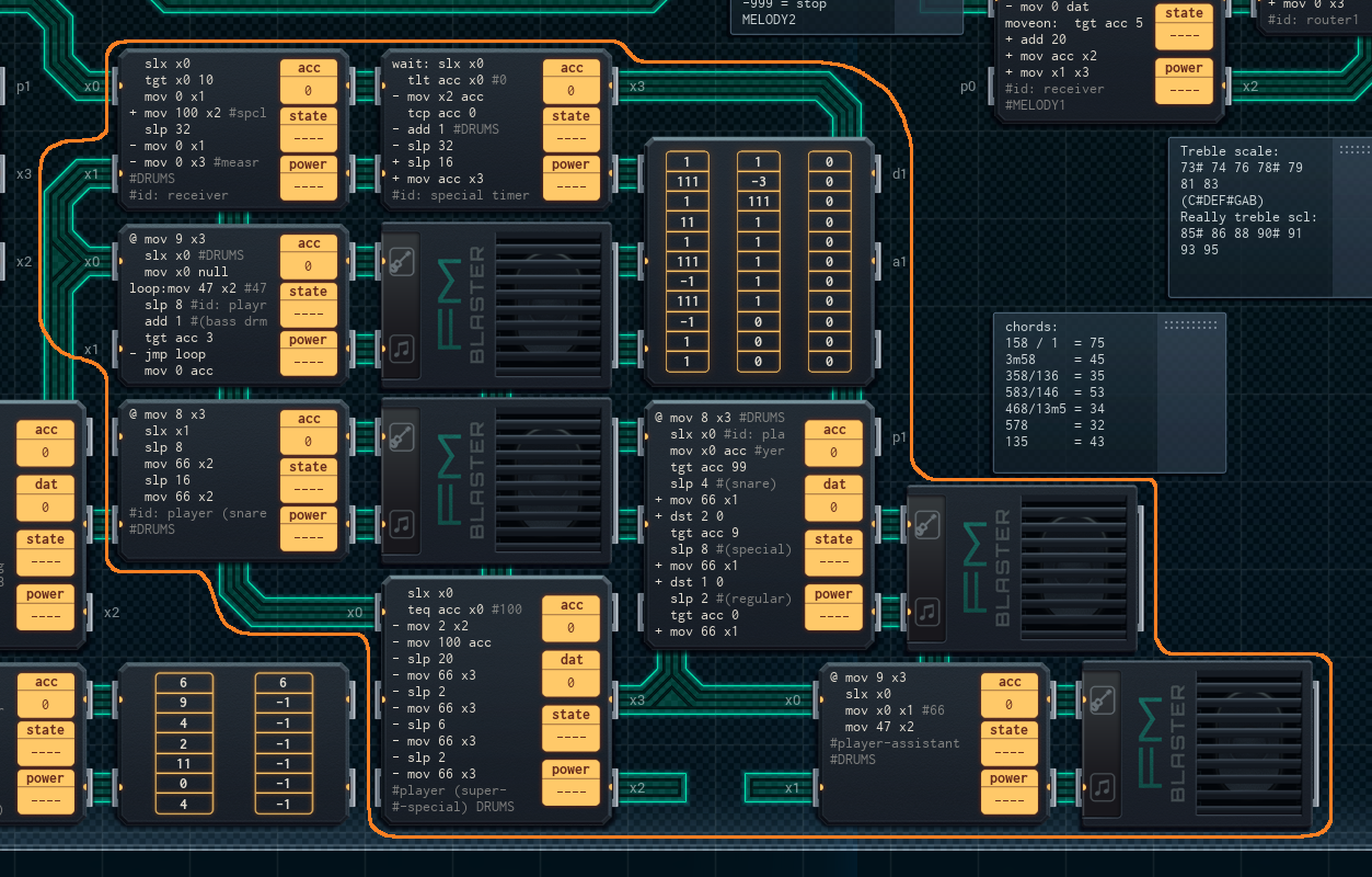
The drums are the last part of the device I added. They’re also the simplest. When a speaker plays other instruments, the note will keep sounding until the attached MC stops it. When a speaker plays a drum beat, the beat stops by itself.
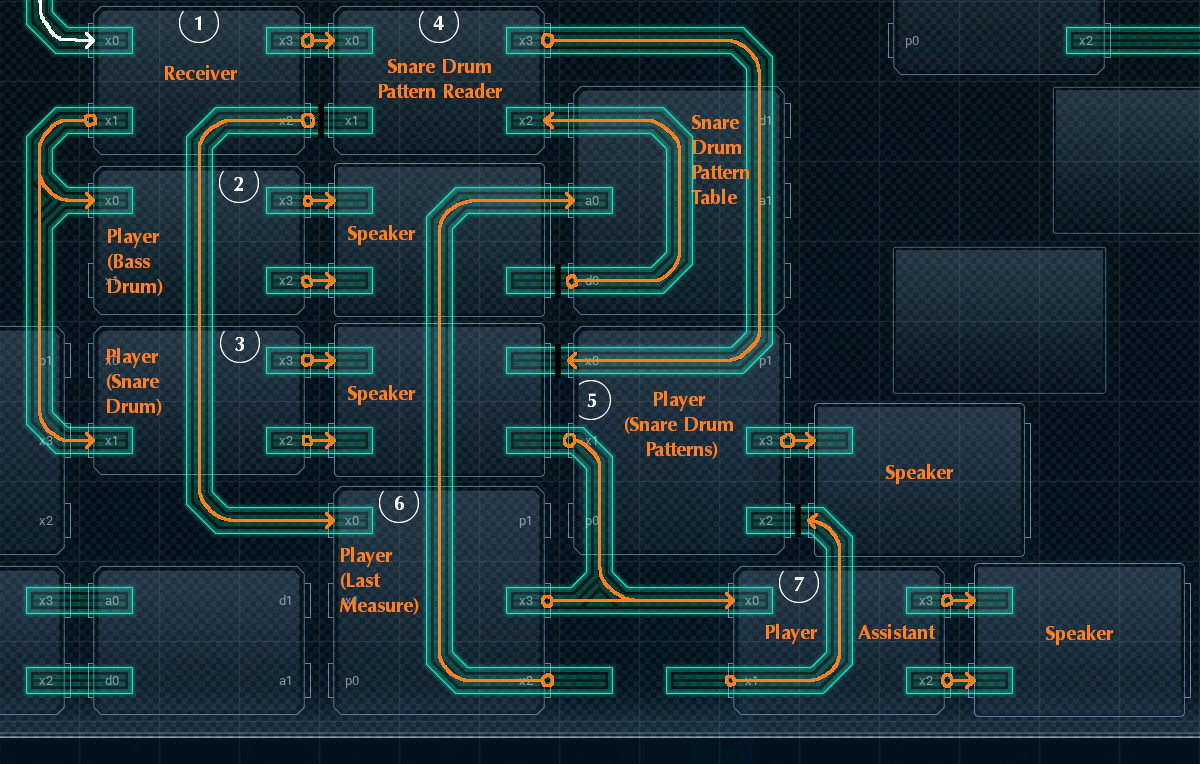
1. Receiver
This Receiver has a total of three jobs, depending on what cue it receives from the conductor. First off: at the start of every measure, it will cue the Players for the Bass and Snare Drums. This is what keeps a regular beat going during the whole song. Second, at the start of every other measure, the Receiver will also cue the Snare Drum Pattern Timer, for fancy drum riffs.
Finally, if the cue is above ’10’, signaling it’s the final section of the song (or about to hit the repeat), the Receiver will notify the Player for the Last Measure as well.
2-3. Player (Bass and Snare Drums)
The Bass and Snare Drum Players might as well be called the ‘Regular Beat Players’. They are responsible for the drum pattern that sets the beat of the song: bass drumbeat, snare drumbeat, bass drumbeat, snare drumbeat, bass, snare, bass, snare…
When cued (at the start of a measure), the bass drum player sounds 4 times (once on every beat in the measure), and the snare drum player sounds twice (on the 2nd and 4th beats in the measure). The bass drum is set up to always back up the snare drum to make the snare drum more audible (which a real snare would be in a performance).
4. Snare Drum Pattern Reader
“Snare Drum Patterns” refers to fancy styling with the snare drum that occurs around the last beat of every other measure. There can be an extra snare beat before the regular snare beat, and up to two extra snare beats after it.
When the Receiver pings the Snare Drum Pattern Reader, the Reader reads from the attached Snare Drum Pattern Table ROM to see the pattern for this measure’s extra snare beats.
1 = one beat after the regular snare beat

11 = two beats after the regular snare beat

111 = one beat before and two beats after the regular snare beat

negative number = skip that many Receiver pings, including the current one. Only the regular snare beat will sound on those measures:

It then sends that pattern to the Snare Drum Pattern Player.
5. Player (Snare Drum Patterns)
The Snare Drum Pattern Player is responsible for decoding the pattern sent by the Snare Drum Pattern Reader, and sending pulses to the Player Assistant (which trigger snare drum hits) on the correct intervals. It does this by testing if the ‘1’ in the hundreds digit of the pattern is present, sending a pulse if so, setting that digit to ‘0’ (which removes it) - and then repeating this for the tens and ones digits of the pattern, each with specific timing values between checks.
The Snare Drum Pattern Player also sets the instrument of the speaker to its right, once, when the device starts up.
6. Player (Last Measure)
The Last Measure Player’s sole purpose is to do a fancy drum riff that bridges the last measure when it’s played the first time - before the repeat that replays most of the piece - with the first measure of the repeated piece. When it’s pinged by the Receiver, it plays the drum riff - but only once! It sets its acc so it won’t play again as the piece ends, where it wouldn’t make sense.
The Last Measure Player outputs its pulses to the Player Assistant.
7. Player Assistant
The Player Assistant fits in a few lines of code that couldn’t make it into the Last Measure Player or the Snare Drum Pattern player. When the Player Assistant is pinged, it sends a pulse to the two speakers attached to it. This codes for a simultaneous snare drum beat, as well as a bass drum beat (to give the snare drum beats body; when I didn’t include it, it sounded weird).
Unlike the Players for most other parts, the Player Assistant doesn’t have to wait before stopping the note - drum beats stop by themselves. This means there’s no timing code in the Player Assistant’s script - just the initial pulse that makes the beats.
The speakers for this part use instruments #8 and #9, “Hi-Snare” and “Bass Drum”.
Total cost for this part: 5x MC4000X (¥15) + 2x MC6000 (¥10) + 1x 200P-33 (¥4) + 4x FM/iX (¥20) = ¥49.
Conclusion
Phew. So that’s my secret project. Let me know what you all think - I hope you like it!
I think I’m going to get one made for Joe.