Part 81: Assignment #AC7: Reactor Status Display
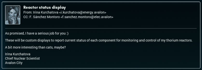
Reactor Status DisplayIt's funny sometimes, how you can run into a person and not realize something really important and relevant about them. In this particular case, it's about Ms. Irina Kurchatova, who I made the cat feeder for back when Avalon City was still growing. At the time, she said she might have a "serious job" for me eventually, but she never said what.
Once the cat feeder commission was over, well— the thing is, I never really bothered to look up Irina's bio. If I had, I probably would have been able to figure out what sort of thing the 'more serious job' could be.
Now, though, I have a very clear answer.
Yep.
To be honest, my first reaction is actually, "I have some questions!"
Why nuclear power? Avalon City currently has a remarkable crop of solar panels, which are supplying the majority of the city's energy needs already - and Avalon City isn't growing any bigger at the present time, as far as I know.
Maybe it's for manufacturing use? Every so often, I do get emails about new types of factory being added to the industrial areas. Still, this project confuses me.
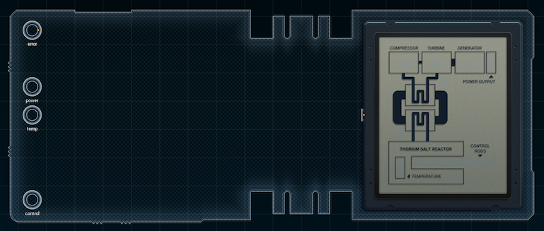
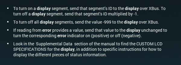
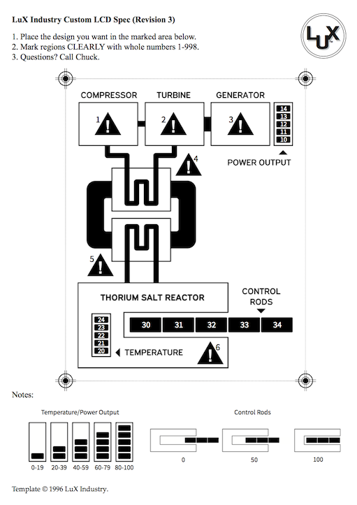
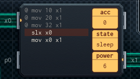
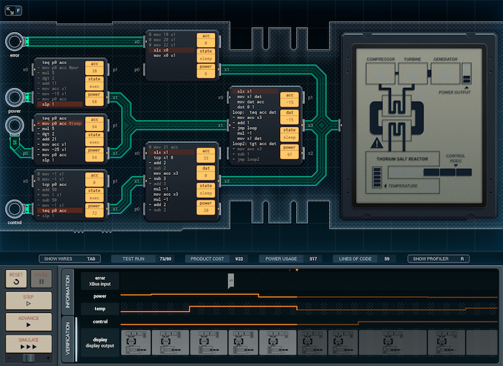
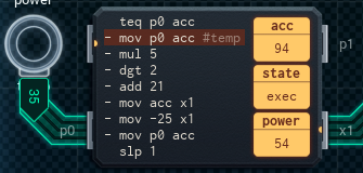
Fortunately, though, the design looks fairly simple. The 'error' code basically writes itself, and the control rods... each time the control rod indicator moves in one direction, a segment at one end of the line is turned off, and another segment at the other end is turned on. Seems straightforward.
[ ~ ]
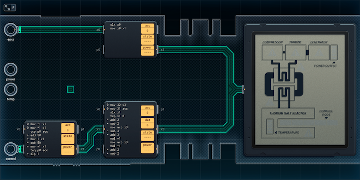
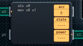
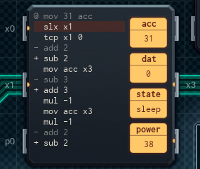
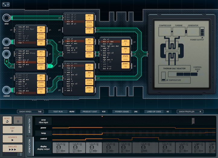
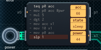
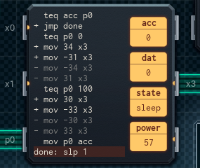
Here's the first half of the design. The error code is handled in the top MC (which just sends any value from the error input on to the display); the bottom two MCs handle the display of the control rods.
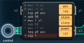
The left bottom MC checks, each time unit, if the control input is the same as last time unit (the previous reading is stored in its acc). If it's the same, it does nothing. Otherwise, it changes its acc by 50 to try and match the control input, sending a pulse to the center bottom MC to say, "move the rod indicator in this direction".
The center bottom (control-rod display) MC takes pulses saying, "move the indicator one to the left" (+1) or "move the indicator one to the right" (-1). Its acc tracks roughly where the center segment of the 'rod' is right now. When the MC gets a pulse, it adds (or subtracts) 2 to get the ID# of the segment that needs to be turned on, to move the displayed 'rod' in the correct direction. It'll send that segment ID# to the display.
Another add/subtract (by 3 this time) gets the ID# of the segment to be turned off, then the MC tacks on a negative sign (to indicate that the segment should turn off instead of on), and sends that to the display as well. Finally, the display MC resets its acc to the center of the lit 'rod' segments, and waits for the next pulse.
I haven't got the power or temperature inputs handled yet, but those are the next step. Onwards.
[ ~ ~ ]
I found out more about the reactor plans. The reactors (plural) are to be housed on their own separate plate, away from the main body of the city as a safety precaution. There'll either be some sort of causeway to get to them, or you'll have to take a boat!
I'm kind of relieved to hear this, to be honest. Nuclear energy makes me antsy, just by its nature.
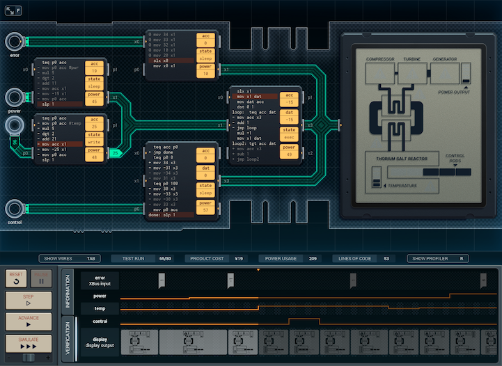
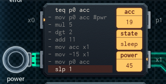
Anyway, I've finished the power-temperature reading MCs, and the design works.
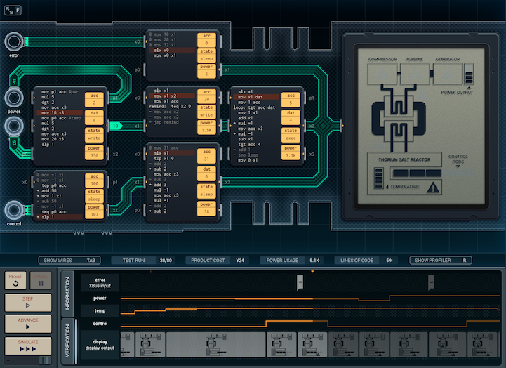
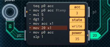
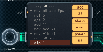
The MCs connected to the error and control inputs are the same as the last version (well, except for a few once-only lines in the error-handling MC that turn on display segments when the device is started). What's new is the three (!) MCs that handle the power and temperature inputs.
The left-center (input) MC6000 reads the values of the inputs, multiplying them by 5 and taking the hundreds digit as a simple way of dividing by 20. It sends each value along to the MC4000 in the middle, along with a '10' or '20' to indicate which set of display elements (power or temperature) needs to be updated.
The middle MC4000 acts as a data cache. It passes the first value (indicating the topmost display element to turn on) it receives from the input MC to the right-center MC6000, and holds the '10' or '20' it receives in its acc. The right-center MC6000 will ask for this held value on a regular basis; the middle MC will provide copies of it until the right-center MC signals it's done.
The right-center MC6000 (the power-temp display MC) is where this all comes together. Because the elements that need to be toggled on or off are always in the range 11-14 or 21-24, the power-temp display MC runs in a loop, with its acc going from 1 to 4. Each round of the loop, the display MC asks the MC4000 it's connected to for the '10' or '20' value, and adds it to acc to get the display element ID# to turn on.
The value the power-temp display MC received before the loop started will be a number from 0 to 4; this signals how many display elements to turn on, and the MC will store this in its dat. When the value of acc as it loops is greater than dat, the MC will multiply the display element value it's come up with by -1 to indicate "turn this element off", instead of "turn this element on".
Once the looping display MC has a display element ID, it'll send that ID to the display, and subtract the '10' or '20' from its acc to reset acc to a single-digit value. Then it jumps to the start loop, if there's more display elements to update.
All of this sounds really straightforward, but there's one teeny-tiny problem with the design: power usage. The design is ¥24 and uses a whopping 9906 average power per run. I get that this is going to be running in a nuclear reactor, but it shouldn't take a reactor to power it! I'm going to have to go over the design and figure out what's making it draw so much energy - and then fix it, of course.
Further updates as designs warrant.
[ ~ ~ ~ ]
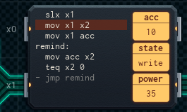
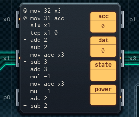
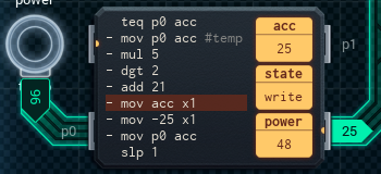
I tracked down the source of the power problem. It turns out it was simple, for the most part: the left-center MC, attached to the power and temperature inputs, was sending updates in the direction of the display every time unit, whether the values of the inputs had changed or not. This new version fixes that.
The large, left-center MC6000 has been replaced with two small MCs, each of which is responsible for one of the two inputs. Each MC uses its acc to determine if the input's value has changed since the last time unit. If so, it sends the input value (divided by 20 with mul 5, dgt 2) to the data cache MC in the middle, which passes it on to the right-center display MC to toggle the correct display segments. The active input MC also sends the '10' or '20' that identifies which line of display segments to edit, like before.
(I was worried that the small MCs might cause a synchronization error by sending updates at the same time if the power and temperature inputs both change at once, so I checked with Irina. She said that for this application, it's possible to set up the MCs so that they wake from slp at slightly different times, which should resolve the issue well in advance.)
I was able to make one other slight improvement to the power-temperature processing MCs - this one is to the middle cache MC and the display MC on the center-right. Put quite simply, the previous design had the cache MC remind the display MC of the '10' or '20' twice when cued: once so the display MC could add it to its acc to get the display element ID#... and once so it could subtract it again to use acc as a loop counter. The second reminder was unnecessary - I was able to remove it by replacing the sub instruction with a dgt 0, instead. This strips out all but the ones digit - same effect, but more efficient.
The display MC was also reminding the cache MC one extra time when it didn't have to, so I rewrote the MCs' scripts to cut the redundant reminder out.
The stats for the changed design are a lot better than before: ¥25, but only 1219 average power per run. While this version is a drastic improvement, my experience tinkering with the power-temperature MC chain leads me to think there's more to improve on.
Right now, any time the power-temp display MC needs to blank out a segment, it multiplies the value of its acc by -1 to negate it, then multiplies the value by -1 again so that the code that checks the loop works properly. Every. Time. If the MC had to blank 4 segments in a loop, that's 8 mul instructions!
It feels like it'd be possible to make things even more efficient, and I'll look into this before I send the design anywhere. With luck, I should be able to give Irina something that's properly optimized once this job is done.
[ ~ ~ ~ ~ ]
The new design runs much better! Even better than I expected, in fact.

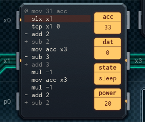
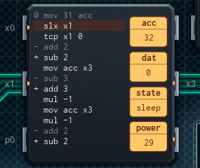
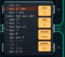
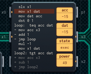
You'll notice that the middle MC - which was caching data before - is now gone. This is because I found a better way of toggling the segments efficiently, using two loops instead of one.
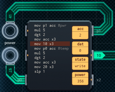
To start with, the power and temperature input MCs on the left now add their '10' or '20' directly to the value, as well as an additional +1 - all the display segments with a lower ID than this number will be turned on. Sending this number to the display MC on the center-right starts the first loop.
The display MC saves the loop-end value in its dat, and gets the loop start ID (either '11' or '21') by digit manipulation (setting the ones digit of the value to 1). Then, it loops through, adding 1 to the ID each time, and turns on all the segment IDs it cycles through.
After that, though, it multiplies the end-point of the first loop by -1 (to indicate to the display to turn off the following segment IDs), gets a second value from the input MC, which will be the end-point of the second loop (either '-15' or '-25'), and continues from there, subtracting 1 to bump up the value of the now-negative acc.
As an example, imagine if you had a power input value of 54. According to the spec, that should be 3 bars on the power gauge. The input MC divides 54 by 20, gets '2', and so sends '13' to the display MC.
The display MC, with its loop, turns on display segments 11 and 12 by sending '11' and '12' (display segment 10 is always-on and can be skipped). The loop does this because the values are less than the '13' the MC received.
Once the MC gets to '13', it multiplies it by -1 to get -13, gets -15 from the input MC as the new input, and turns off segments 13 and 14 by sending '-13' and '-14' to the display. (There's no segment 15 to target with a '-15', and the MC stops the loop once its acc is at the end value.) Finished!
This version betters the previous design substantially, coming in at only ¥22 and 814 average power per run. I think I've improved the center line (with the power and temperature inputs) as much as I can - but all this messing around with numbers has given me an idea for how to make the MCs connected to the control input more efficient.
I think I'll test out what I've got in mind and see if it works - and then call it a day.
[ ~ ~ ~ ~ ~ ]
And here it is - the pretty-much-final version.
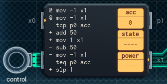
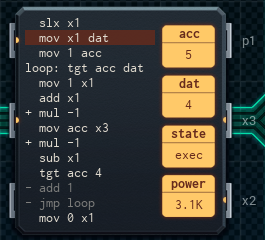
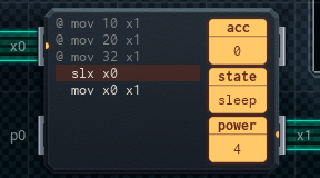
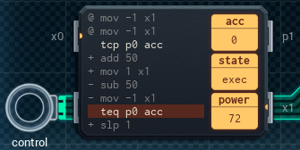
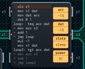
As promised, the only difference between this version and the last one is that I've reduced the control-input handling part of the device to a single MC. It turned out a lot of the old way to handle the control input was redundant, if you think about the 'control rods' displays segments as two pairs of segments apart from each other, along with a central segment that's always on.
Segment 30 (far left) is always on when segment 33 (center right) is off, and vice versa.
Segment 31 (center left) is always on when segment 34 (far right) is off, and vice versa.
Segment 32 (dead center) is always on, and is turned on by the error-handling MC as part of its initial script (it's where I had free space). We can ignore it when changing the control-rod display.
So, the new control-rod handling MC checks the control input to see if it's different than last time unit, then (if so) decides which segment of each pair should be on, and which should be off. It sends that information to the display, then goes back to sleep to wait for the next time unit. It's pretty straightforward.
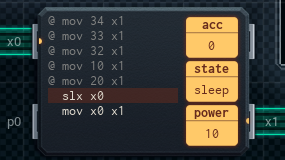
(A side effect of this is that I had to add a few more one-off lines to the error-handling MC, to set the control rod display segments' starting state when the device is turned on.)
This version is ¥19, and uses 761 average power - and compared to the first working version, it's a design I can really be proud of.
Time to make it official.
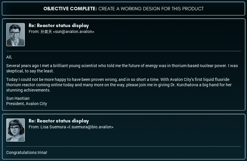

Congratulations to Irina on her commendation!
That said: More energy than we could ever need, huh? I still want to know what this is all for. If it's manufacturing, what's being made? If it's not, what sort of thing would create such an energy draw?
I might have to look into this - I'll post here if I learn more.