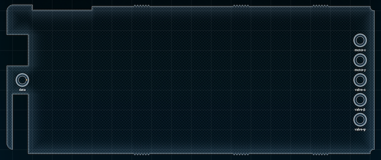
Part 84: Assignment #AC9: Scaffold Printer
Scaffold PrinterIt turns out that joining the NETHUNS project was the relative end of silence in my inbox. I've been getting a lot of chatter regarding interfaces this, neural computing that, and so on. And today, a new project showed up.

As far as I can tell, this design appears to be at the forefront of neural network research: not computing with the AI constructs known as "neural networks", but with actual networks of neurons (or something that looks a lot like them - maybe mock neurons). The project itself looks interesting, and the design looks pretty simple. Or, well, it did. Then I took a close look at the specification.
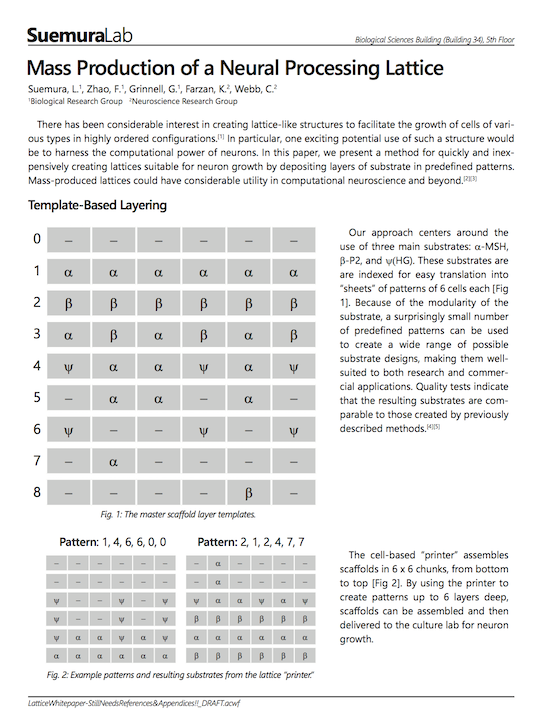
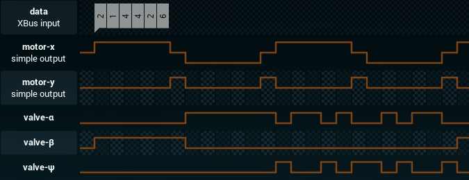
If there were just the 9 patterns listed in the article, I'd probably be able to do something clever and make it so that each pattern requested had a different code path. But that would require the scaffold printer's "print head" to always move from left to right. It doesn't. In the spec, you can see that it prints the first row left to right, then reverses direction and prints the second row right to left, then the third left-to-right, the fourth right-to-left again, and so on.
In short: the device has to not only store the 9 patterns listed, but also what they look like when printed in reverse order. Patterns 0-2 are the same backwards and forwards, but the rest aren't - once you count all the reversed variants, there's some 15 unique patterns to distinguish from, counting the blank one (Pattern 0).
The amount of information that needs to be stored is probably going to force any and all ideas for clever plans out the window... and I'm honestly not sure where to start. I'll try taking a stab at things and see where I end up.
[ ~ ]
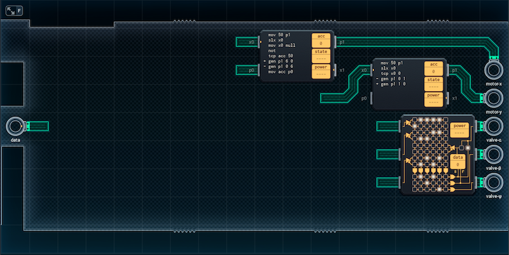
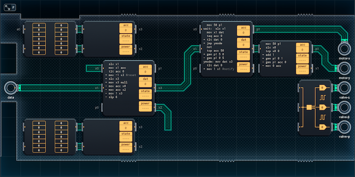
This is my earliest attempt, and while the MCs attached to the motor outputs are a good start, the PGA33X6 was officially a mistake.
I had assumed that with the PGA, I'd be able to separate the patterns into chunks, then use the PGA as a sort of translation table, maybe in concert with some logic gates. The problem with that: the PGA only has eight conceivable input states, so I'd have to do a LOT of preprocessing to get the input to a set of 8 state-chunks - and not only can I not see any obvious way to turns the required patterns into something that the PGA would be able to use, but by the time I'd done that much preprocessing, the PGA itself would be useless.
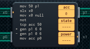
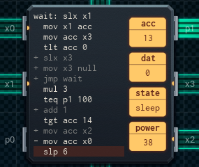
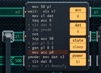
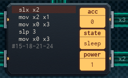
I have, however, gotten a start on the motor MCs. The upper one handles horizontal movement of the print head; each time it's triggered, it pulses motor-x for six time units, moving the head all the way right (or left). It uses its acc to keep track of the direction it should move, and so will move in opposite direction each time it runs.
The lower motor MC is set up to handle vertical print head movement, but it's pretty crude for the moment. If it's notified with a positive number, it moves the print head up by pulsing motor-x to 100 for one time unit. If the MC receives a negative number instead, it moves the print head down by pulsing motor-y to 0 for a time unit. There's no functionality for resetting the print head to the lowest position yet, but that'll come soon.
With the PGA approach fallen through, I'll have to come up with another approach. I'll try to see if there's any similarities among the patterns that I can use to the design's advantage - but it'll be tough.
More soon.
[ ~ ~ ]
I've made a little more progress - though my 'second approach' to decoding the patterns also fell through.

I had planned to break the patterns into three-time-unit chunks, and control the what valve was to be turned on, and whether a valve was to be turned on, separately. This was initially based on my observation that Patterns 4, 5, and 6 are the same pattern - except Pattern 5 has blanks instead of Ψ (Y), and Pattern 6 has blanks instead of α (A).
Here's how I had it mapped out:
I had a total of seven valve-value chunks:
AAA, BBB, ABA, BAB, YAA, AYA, and AAY.
I also had a total of eight valve-activation chunks:
111 (all on), 000 (all off), 100, 101, 001, 011, 110, 010.
From there, it was just a matter of coding patterns to pairs of value-power chunks:
0: [any]-000, [any]-000 (same in reverse)
1: AAA-111, AAA-111 (same in reverse)
2: BBB-111, BBB-111 (same in reverse)
3: ABA-111, BAB-111
(reverse: BAB-111, ABA-111)
4: YAA-111, AYA-111
(reverse: AYA-111, AAY-111)
5: [YAA or AAA]-011, [AYA/ABA/AAA]-101
(reverse: [AYA/ABA/AAA]-101, [AAY or AAA]-110)
6: YAA-100, AYA-010
(reverse: AYA-010, AAY-001)
7: [AAA/BAB/YAA/AAY]-010, any-000
(reverse: [any]-000, [AAA/BAB/YAA/AAY]-010)
8: [any]-000, [BBB or ABA]-010
(reverse: [BBB or ABA]-010, [any]-000)
This is where the grand idea fell apart. I could see a few shortcuts - like being able to use any of AAA, BAB, YAA, or AAY as a value chunk in Pattern 7 - but I couldn't figure out a good way to code this all into a translation table. So, instead, in this section, I'll tell you about the new MC I added, which handles input.
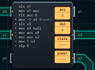
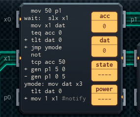
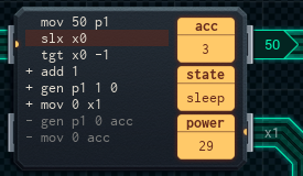
The new MC checks if the input is a line (0+) or a reset packet (-1). If the input is for a line, it copies the value out to x0 and x2, which will go to the MCs that will determine what patterns to output. (These MCs have yet to be installed and coded.) In either case, it will also send the value to the main motor MC (the MC6000 on the top right).
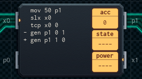
The main motor MC has been upgraded slightly. Not only does it pulse for 5 time units, instead of 6 (I had the timing wrong before), it will now save the input it gets and pass it on to the secondary motor MC on the far right. If the input was a reset (-1) packet, it will also notify the input MC once the print head is done resetting; the input MC pauses when it receives a reset packet, so the pulse from the motor MC lets it know that it can start reading input again.
The secondary motor MC now tracks the height of the print head in its acc. If it receives a reset packet, it will now lower the print head to the lowest level in one movement.
So, as I predicted above: clever solutions have failed. Even only slightly clever ones. It's time for me to go the simple way, and use the ROM chips I put in for the translation table to hardcode the expected output.
It's an ignoble way to build the device, but it'll work, and it might even be efficient in the bargain. We'll have to see.
There's no way forward but to build it!
[ ~ ~ ~ ]
Here it is! It got a lot more complex-looking, but it's the same device at heart.
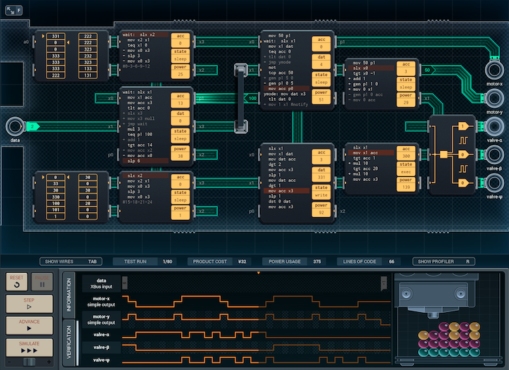
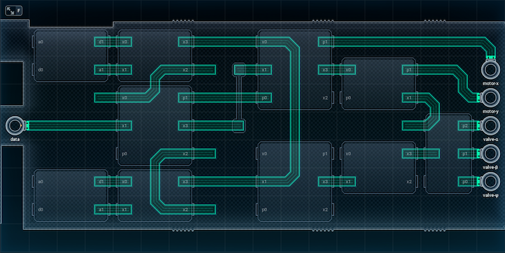
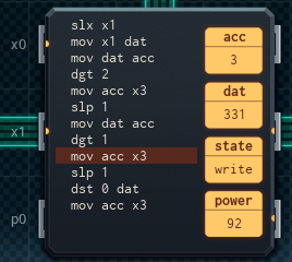
When the input MC gets data now, it turns it into a memory address by multiplying by three. Then, it sends the address to one of the two pattern-reader MC4000s attached to ROM chips (in the top and bottom left). Those MCs will use that memory address to get the correct pattern of valve outputs.
Backwards patterns are also handled by the input MC. The main motor MC uses its p0 simple output to let the input MC know whether it's a normal or reversed line. If it's a reversed line, the input MC will add 1 to the memory address before it sends it off to the pattern-reader MCs. This works because each of the patterns in the article has a second half that is the same in reverse.
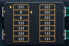
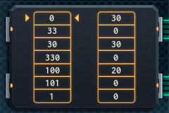
So, in the memory chip, each pattern is stored in three memory cells, in this order: (first half of pattern) (second half of pattern) (reversed first half). The pattern-reading MCs attached to each ROM chip will output two values out of those three. If it's the normal pattern, it reads the first and second cells. If it's the reversed pattern, it's the second and third cells.
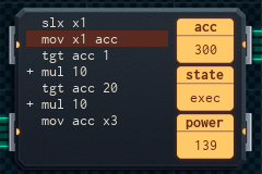
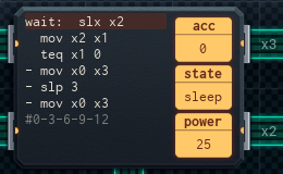
The pattern reader MCs' output lines are connected to the primary decoder MC, which is the MC6000 on the lower center-right. This MC functions a lot like the decoder MC from the brain-computer interface: it takes a three-digit value and turns it into three single digits. The digits are fed to the secondary decoder MC (bottom right) one at a time, which toggles the correct valves with the output expander.
The motor MCs are mostly the same as last design, with just a few slight tweaks:
• The big motor MC now reports on its p0 whether it's a reversed line or not. The input MC reads this to determine which pattern to use, as mentioned above.
• The small motor MC turns off the valves after each line has been successfully printed. (There was no space for the instruction in the other MCs.)
And that's the design! It's actually more efficient than I expected, clocking in at ¥32 and 636 average power per run. I'm pretty sure Lisa is going to be happy with it.
I wonder how many of these they're planning to make? Is this going to be more research lab equipment or production equipment?
I'll have to ask next time we're in the same room.

Overall, this project was kind of weird. It wasn't hard in the end - it was only difficult when I was trying to be clever about it. Once I just bit the bullet and hardcoded the patterns, it became really straightforward.
I guess there's some kind of moral to be had there, but I'm not sure what it is - but for now, I'm going to take a break. A group of people ended up following in the footsteps of the Sushirobo concept and made a Mexican restaurant! And I'm about to go see it.
Avalon City is becoming more intriguing, challenging, and comfortable every day...