Part 53: Engineer's Corner #6: The PGA33X6 Demystified
Engineer's Corner 6: The PGA33X6 DemystifiedSo ever since Carl ended up with a pocketful of them, there's been some PGA33X6es rattling around in our storage bins. I meant to play around with them and figure out how they work, and this meat-based printer was the perfect excuse to do it. And now you get to find out, too - I'm sure there's an(other) English-speaking tech somewhere who's gotten the same headaches I have - but found nothing on the Internet about how to use it.
Let's fix that.
I'm going to break down the PGA section-by-section, as it looks more complicated than it is.
Input Lines

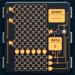
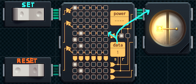
The bulk of the PGA is made up of four input lines, three of which are attached to the input pins on the left. A single input line looks like this:


(The image on the left is how it looks in when the simulator is in design mode. The image on the right is how it looks when it's running.)
That triangle on the left splits the input into two rows. The lower row is active when the input is off, and the upper row is active when the input is on.
You can set one of the two squares in each column of the input line to white (active), but not both.
The third set of input lines in the grid, the one coming from the right, is a special set, and we'll cover it in more detail in a bit (see 'Data Register and Latch Input').
Output Lines

Each column in the PGA's input lines grid is attached to what's effectively an AND gate. If the PGA's inputs are set such that all the white squares in a column are on active rows, then the AND gate activates, turning on any output line below it where there is a white square in that column.
Effectively, the AND gate associated with a column can be connected to up to four inputs, and will trigger when all the connected inputs are in the correct state.
The three output lines correspond to the three output pins on the right side of the PGA. If an output line is on, the associated output pin will be on, and vice versa. (Note that for the topmost pin, there is an alternate mode that is not directly connected to the top output line - see 'Upper Output Source Switch').
Basic PGA Use
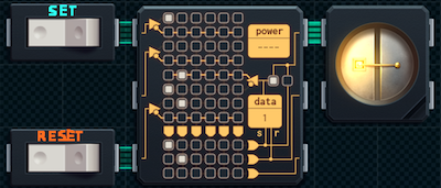
With just the input and output lines, you can use the PGA like a bunch of AND gates that have been connected to a bunch of OR gates: you set the pattern of input you want matches in the input lines grid, then set the pattern of output you want in the output lines grid. Hook up some inputs and outputs, and you're golden.
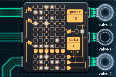

(This image shows how the pattern of inputs in the example (only the top input pin is active) results in a single column being active, leading to the top and bottom output pins being active.)
But the PGA can do more than just act like a simple logic gate construct.
Data Register and Latch Input

The PGA's data register can hold a single bit of information: a 0 (off) or 1 (on).
The data register changes when one or more of the output lines are activated. If the top output line (set) is activated, the register changes to 1. If the middle line (reset) is activated, the register changes to 0. (If both the top and middle lines are activated at the same time, the top line wins and the register chances to 1.)

The data register is connected to the third input (which I'm calling the 'latch input') in the PGA's input grid. Aside from the bit about being connected to a different source, the input works the same way as the others.
The data register can also be connected to the topmost output pin on the right of the PGA (see next section).
Upper Output Source Switch

This switch determines what the topmost output pin on the PGA is connected to. If the switch is set to the right position (normal mode), the pin will use the state of the top output line in the grid. If the switch is set to the left position (data mode), the pin will use the state of the data register instead.

Advanced PGA Use
The data register, and the associated input line, lets you use the PGA to set up a construct called a latch. A latch comes on when triggered by a certain input (or pattern of inputs). However, the latch will not go off if the input is removed, or the same pattern is applied again.
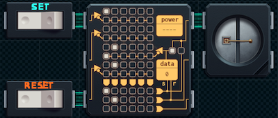
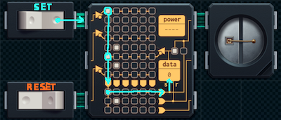
The latch will only go off if a different pattern is applied.
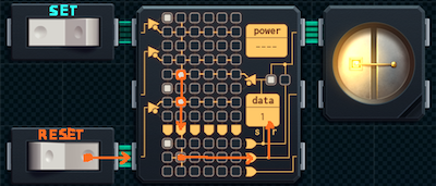

(You can set it up so that the latch turning on triggers the 'off' pattern, and it turning off triggers the 'on' pattern - in which case the latch will oscillate between on and off every tick. Doable, but not that useful.)
The latch input in the input lines grid lets you use the value of this latch as another input to the basic AND-gates-into-OR-gates setup, allowing decently complex behavior.
Power Meter

It's no secret that the PGA is listed as "not for low-power applications" on the datasheet. After some testing, I found out the exact nature of its power draw:
The PGA33X6 uses 3 units of power each time any input changes (this includes the latch input). This applies whether or not the output changes, the data register is affected— whatever. It's just, whenever the input to the PGA changes, boom. 3 power.
On the bright side, if you don't use it much, you can get complex behavior without much power usage. On the downside, logic gates will always be more power-efficient. (It is entirely possible to make a latch using 3 logic gates, and the rest of the PGA's functionality with ANDs and ORs is also doable if you can spare the board space.)
So now you know how the PGA33X6 works. Go forth and logic!
[ ~ ]
paragon1 posted:
You're going to get complaints that your windows don't work because they never open (they will be working fine).
Well, you have to expect bugs like this if you're using windows.
mercenarynuker posted:
That sliding window looks more like a toddler guillotine.
Thus the need for the hardware to include a nonremovable screen on the inside. Or make it so that the window only runs when the screen is in place, through an interlock.
limaCAT posted:
This came up in my Youtube recommendations...
https://www.youtube.com/watch?v=Uj-nBFsQLkI
Wow. That's a heck of a gleeful misuse of the prototyping area.
...kinda like what I'm doing with it.
HenryEx posted:
It took me a while of futilely moving about code lines, but...
...if you don't care about energy efficiency and are content to run through the whole code and test for the first loop every time, you can just cut out the jmp for the second loop and fit it all on a MC4000.
If you want to see what it looks like here's a spoiler
https://i.imgur.com/ZvxeCun.png
")
Well done, sir! A fine solution. Power might not really be a consideration if they installed the change machines as in-counter fixtures, etc.
Ratoslov posted:
What kind of nutbar makes hexagonal intersections?
Bees do.

Dareon posted:
Yeah, this sounds feasible. High-density food production, high occupancy, automated or high-traffic transit networks. Could be a spaceship. Could be a moonbase. He could just be trying to improve on Kowloon Walled City.
I stand by my 'founding a city' hypothesis, and I'm glad to see other people are joining in.
Also, Kowloon Walled City is a fascinating topic.
Aabcehmu posted:
Do we know for sure that Sun Haotian isn't just straight-up lying about what the microcontrollers are going to be used for?
That's the thing: I can't be sure. But we're three Sun projects in, and they add up to a coherent theme in my book - I can't think what the alternative would be.
a computing pun posted:
If you lie to your engineers about the nature of a given request (as opposed to lying about the purpose) then you take the significant risk that they deliver something that does what you asked for but not what you actually want because your fake spec and real spec weren't similar enough... [...]
Sun Haotian seems like a fairly savvy operator; given a choice between risking vague data on individual parts of his project leaking and risking unknowably large spec-based design errors leaking into his project, he'd certainly choose the former.
To continue my answer to the last question, this post explains another good reason (why he's not lying) better than I ever could. Engineering has enough edge cases that, unless you're going to specify what to do with them, it's "undefined"— aka "engineer's choice". Are you going to lie about your project and let the undefined in?
TooMuchAbstraction posted:
...we haven't heard from Joe in a bit, have we?

Joe's back in the office! He's... I dunno. A little more quiet? Thoughtful? This isn't saying he doesn't get exuberant or anything, but I think he's changed a little.