Part 63: Secret Project: Ra, Ra, Rasputin! - Part 1
Secret Project: Ra, Ra, Rasputin!So, those of you who have been following this blog for a while have noticed I've been mucking about in my spare time on something I call my 'secret project'. Well, guess what? My secret project is now here - and I'm ready to share it with you.
Presenting: Ra, Ra, Rasputin.
A fully multitracked version of Rasputin by Boney M, played on the finest (?) in electronic instruments.
Set the video quality to 1080p HD for best results.
https://www.youtube.com/watch?v=dZVrbpQoqg0&hd=1
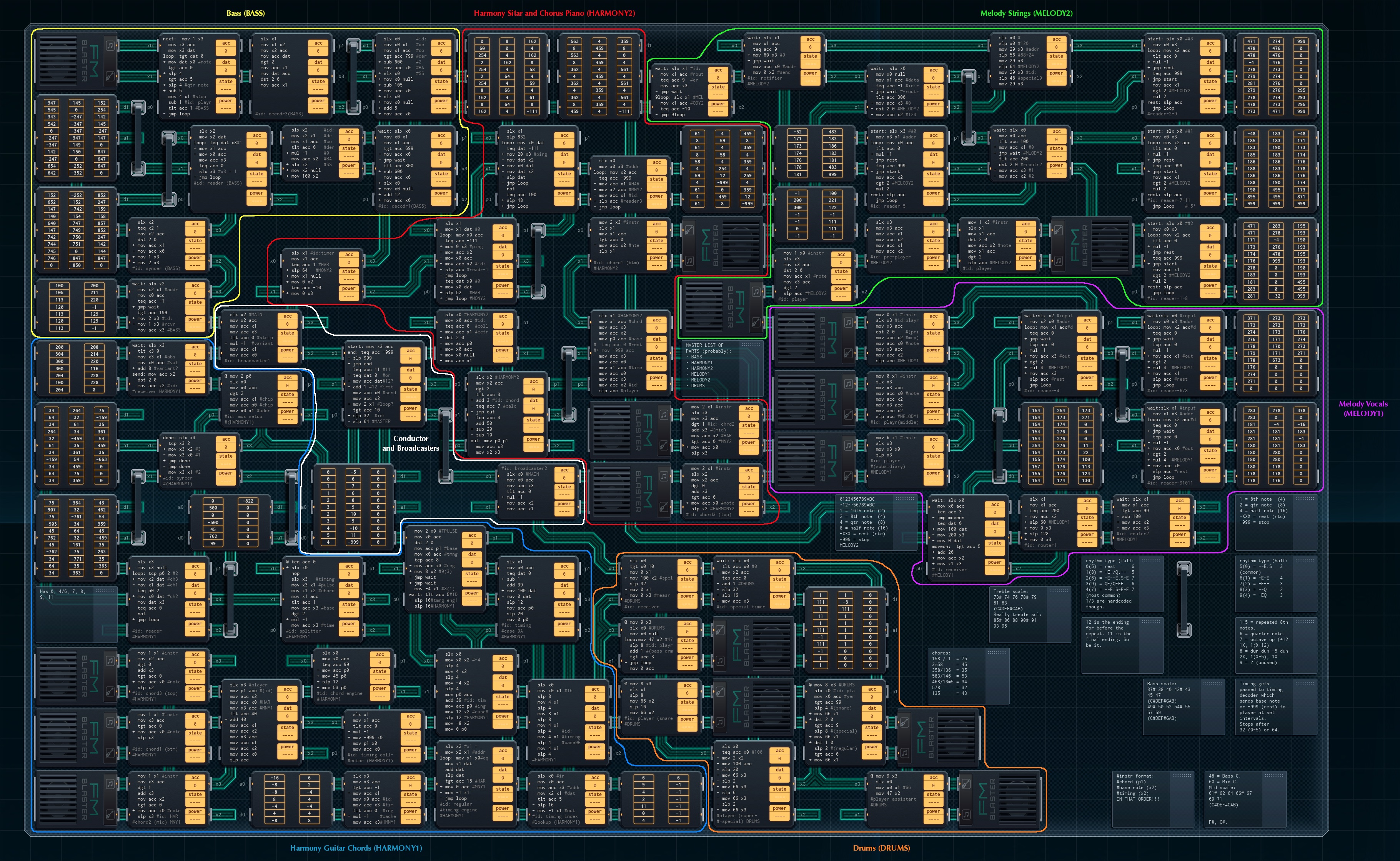
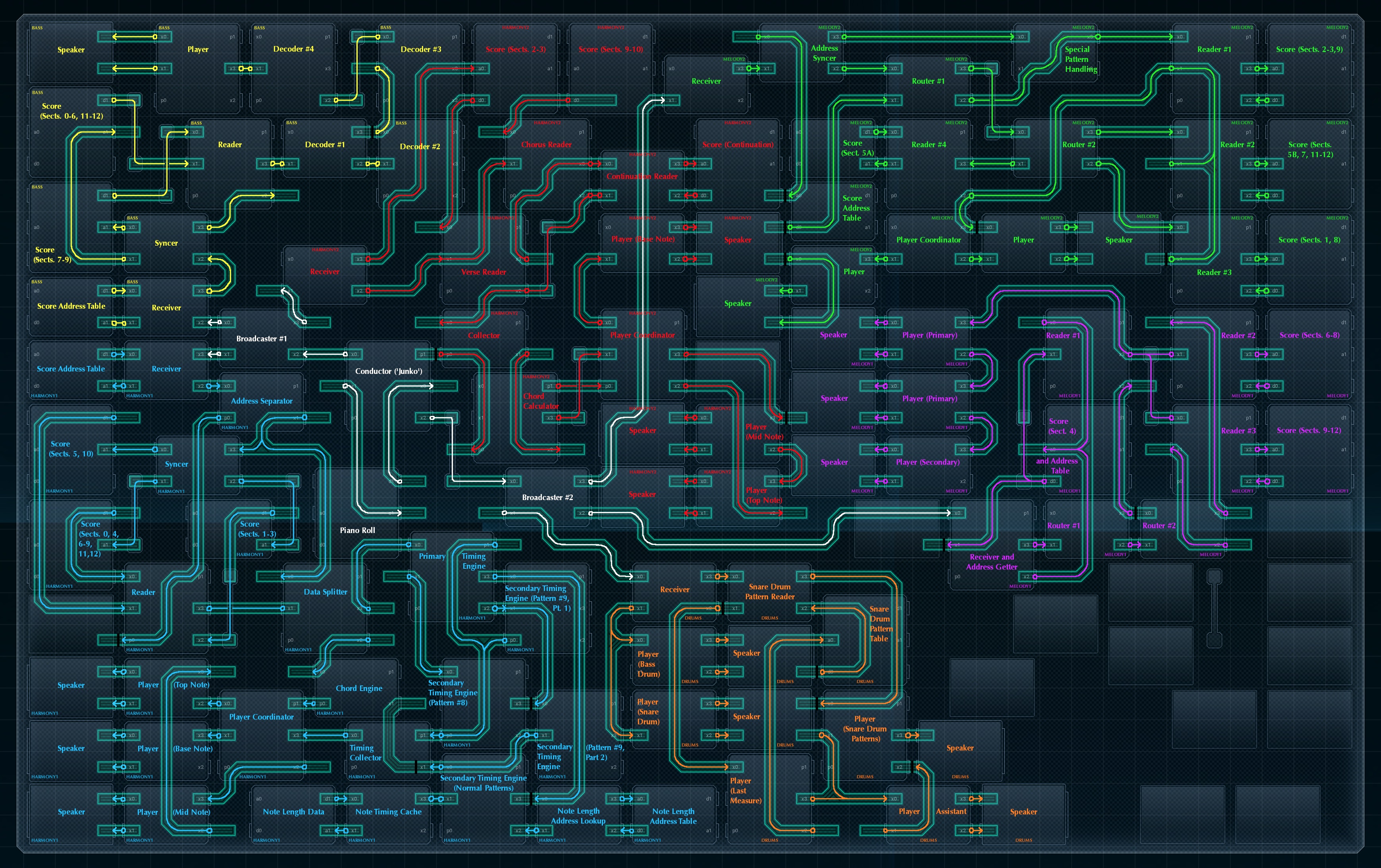
As you've probably noticed, that is not the full size blueprint or wiring diagram - those are at the following links, 'cause they're just too darn big. Expect a 3500 x 2200 image at the end of each link.
Full-Size Blueprint Full-Size Wiring Diagram
Download a copy of this project (only works if you've modded your simulator)
You can click on every other image in this post to get a full-sized version of it.
This device uses 4 MC4000s, 35 MC4000Xs, 28 MC6000s, 7 200P-14s (small ROM chips), 15 200P-33s (big ROM chips), 16 FM/iXs (speakers), and 12 bridges (not counting the unused one in the corner), for a total cost of ¥411. The simulator doesn't track power usage if you don't have an active spec loaded into it, so I don't have any stats there.
There are 32 time units per measure, and the piece is in 4/4 time, so a quarter note is 8 time units.
Backstory and General Construction
I got the idea for this project when I ran into a video on the web of Rasputin on a player organ. I was officially Inspired. After a fruitless attempt to get a MIDI file from the owner of the organ*, I found a MIDI file of the song elsewhere and began work.
*The organ guy explained that player organs use their own unique scales. Any MIDI file he could provide would be useless.
After a quick look at the MIDI file, I mentally broke the piece down into six parts: the bass line (BASS), main harmony guitar (HARMONY1), the sitar that replaces that guitar at one point as well as the piano chords during the chorus (HARMONY2), the vocal line (MELODY1), the strings (MELODY2), and drums (DRUMS). Each of these parts is marked out in its own color on the blueprint and wiring diagram - I'll explain each separately below.
(There's also one extra part in the finished device: a few 'MAIN' conductor MCs that keep everything running together, and are responsible for cueing everything else.)
For each part of the piece, I followed roughly the same procedure:
[1] Open the MIDI file in a music editor, and see if there were any patterns in the notes. (I decided not to include the B section of the song or the chorus after it - if the player organ guy could get away without it, I could too.)
[2] Make an encoding scheme that would store this particular part efficiently. (Most of the parts use different encoding schemes.)
[3] Put the encoded part in a ROM chip - or two or three. (Usually three.)
[4] Make a design to play the part when cued by the conductor MC.
[5] Test the design to see if it worked.
[6] Fix any bugs that cropped up.
[7] Repeat [5] and [6] a few times until everything worked.
And then I'd be one step closer to a finished device.
Challenges, Big and Small
There were two big challenges in building this. The first was finding enough space. I had to install an unofficial mod to my simulator to get it to recognize boards this big at all - and since the project's using almost all the space, I can only conclude the 'software update' was worth it.
The second big challenge, more seriously, was lag. I suspect the reason the simulator never had the native capability for large boards is because once I had about 4 parts of the song in (covering 2/3 of the board or so), the playback started to lag and slow down below the song's tempo. I solved this by halving every unit of duration in the song's timing, effectively doubling the speed! From there, I was able to get the right tempo by adjusting the 'simulation speed' slider. Even so, the simulator can still lag a tiny bit during playback - more if you're running other applications in the background.
There were a few little challenges, too. No offense, Mountleaf Sound Concepts - but your instruments suck! They sound like a computer with a cold playing a kazoo. I did the best I could, though, picking goodish-sounding instruments (and sometimes mixing instrument sounds together).
List of All Score Sections
Every so often, in the rest of this post, you’ll see me refer to parts of the piece by a section number. I split the piece into internal sections, and this list explains what each refers to.
The list includes the relevant vocals from the song’s first verse, in case you’re following along with the original Boney M recording.
0: Intro chords
1: Rising opening guitar melody (repeat goes from here)
2: Sitar melody (first half)
3: Sitar melody (second half)
4: Vocals (“There lived a certain man / in Russia long ago…”)
5: Vocals (“He was big and strong / in his eyes a flaming glow.”)
6: Vocals (“He could preach the Bible like a preacher” / “But he also was the kind of teacher”)
7: Vocals (“Full of ecstasy and fire,”)
8: Vocals (“Women would desire.”)
9: Chorus (“Ra, Ra, Rasputin! Lover of the Russian queen!”)
10: Chorus (“There was a cat that really was gone!”)
11/12: Last measure - piece repeats (12) or ends (11) after this.
Part 0 - The Conductor
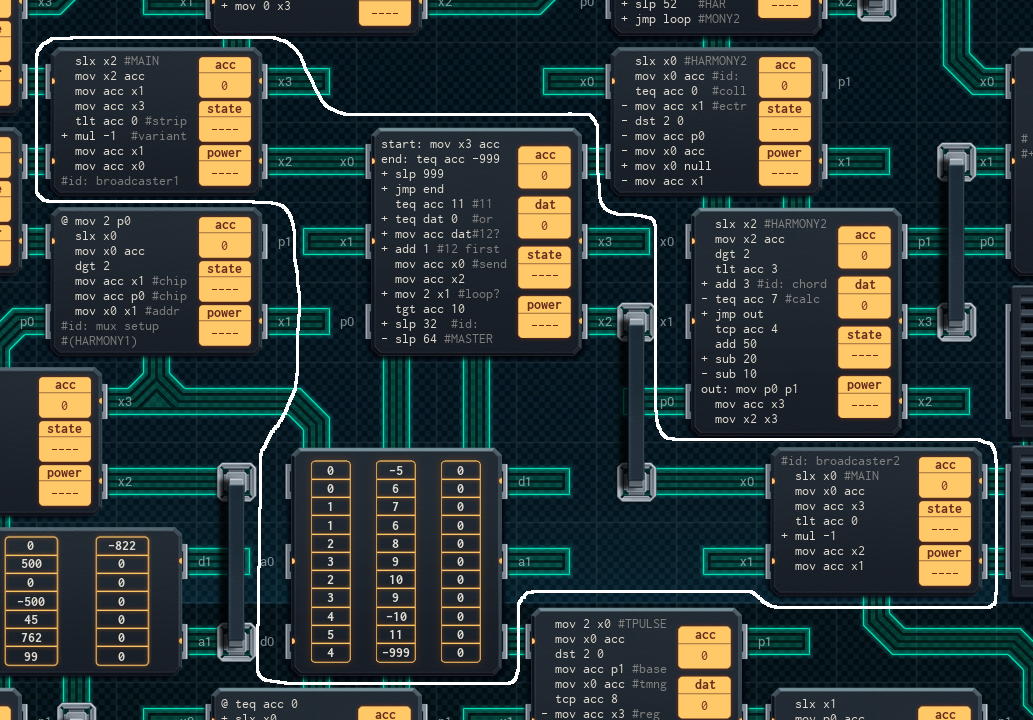
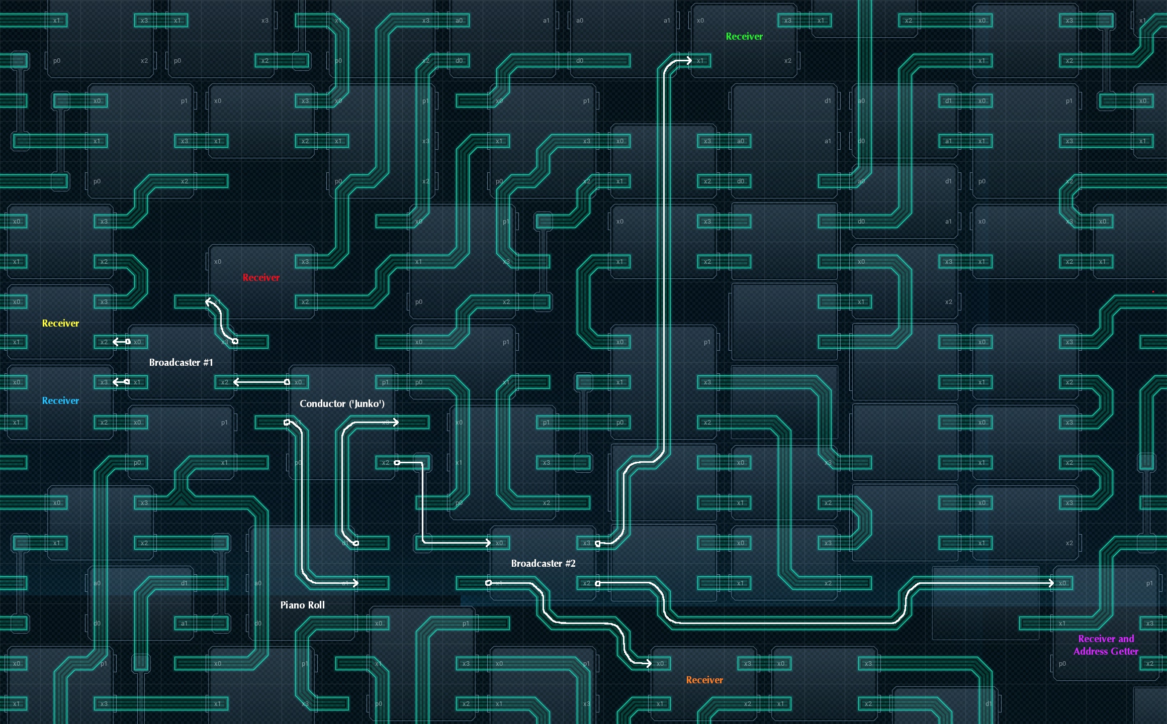
This is the heart of the project, consisting of the main conductor MC (which I nicknamed 'Junko' after a character in another famous Let's Play), two broadcaster MCs, and a memory chip that holds the 'piano roll'. Every 64 time units (2 measures), Junko reads off a new value from the piano roll and sends it to the broadcasters, which cue the various other parts of the project.
Complications
There's a bit of a wrinkle once the piano roll hits the cell with the value `11`. This is the last section of the piece, and is only one measure long. The first time this happens, Junko will send '12' (not '11') to the broadcasters, then rewind the piano roll to repeat most of the piece. The wait time on this section is adjusted from two measures to one so there's no gap before the repeat.
(As an aside, the repeat made my job a lot harder. Instead of writing scripts for the rest of the MCs that could do only-use-once tricks, I had to make everything able to run at least twice.)
Once a value reaches the broadcasters, they copy it to the receiver chips of the rest of the project (as shown in the wiring diagram). There's a few wrinkles with this process, though.
First, note the negative numbers in the piano roll: they indicate a variation from the original section with the matching positive number (so '-5' is 'variation of section 5'). Not all parts of the player read variants, so the broadcasters remove it before sending. The Bass, Vocals (MELODY1), and Drums parts don't use variant data, while the rest do.
It's also worth noting that the Melody Guitar (HARMONY1) part gets sent its cue twice: once with the variant number and once without. HARMONY1 is the most complicated part of the entire project, so I'm not surprised, on retrospect, that I did custom stuff cueing it.
Finally, fun fact: There’s code in the conductor to stop the project after the repeat plays through, but it never gets used! The reason for this is that the device actually stops due to the bass player part blocking after the entire score has been played. This is at least partially because of a dubious design decision while I was creating that part…
Total cost for this part: 2x MC4000X (¥6) + 1x MC6000 (¥5) + 1x 200P-33 (¥4) = ¥15.
Now, on to the inner workings of each part of the device.
Part 1 - The Bass Line (BASS)
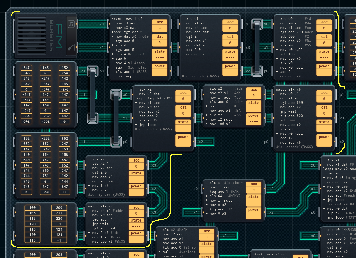
The bass line was the first part I constructed. On the face of it, it's fairly simple - the bass line only plays one note at a time, that note is often repeated, and it stays within a range of a few octaves or so. The only real wrinkle with the part is that I compressed the notes to fit into two large ROM chips, so a large amount of the BASS part's footprint is devoted to decoding the compressed data. Here's how it works.
Bass Note Encoding
Each cell in the two big ROM chips on the left is a sequence of notes. The leftmost digit of the cell keys for the note pattern, and the other two digits set the pitch of the note (this number is passed directly to the speaker).
Different first digits key for different note patterns:
1-5 = 1-5 repeated eighth notes, all of the same pitch:

6 = single quarter note (♩)
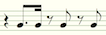
7 = two eighth notes (♫), the second an octave higher than the first:

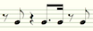
8 = four eighth notes (♫♪♪). The third eighth note is a fourth lower than the other three:

If a cell has a negative number, the device part adds an eighth rest (
 ) before reading the next cell; if the cell is a 0, the device part considers this section to be all done, and waits to be cued by the conductor again (well, sort of - see below).
How It All Works
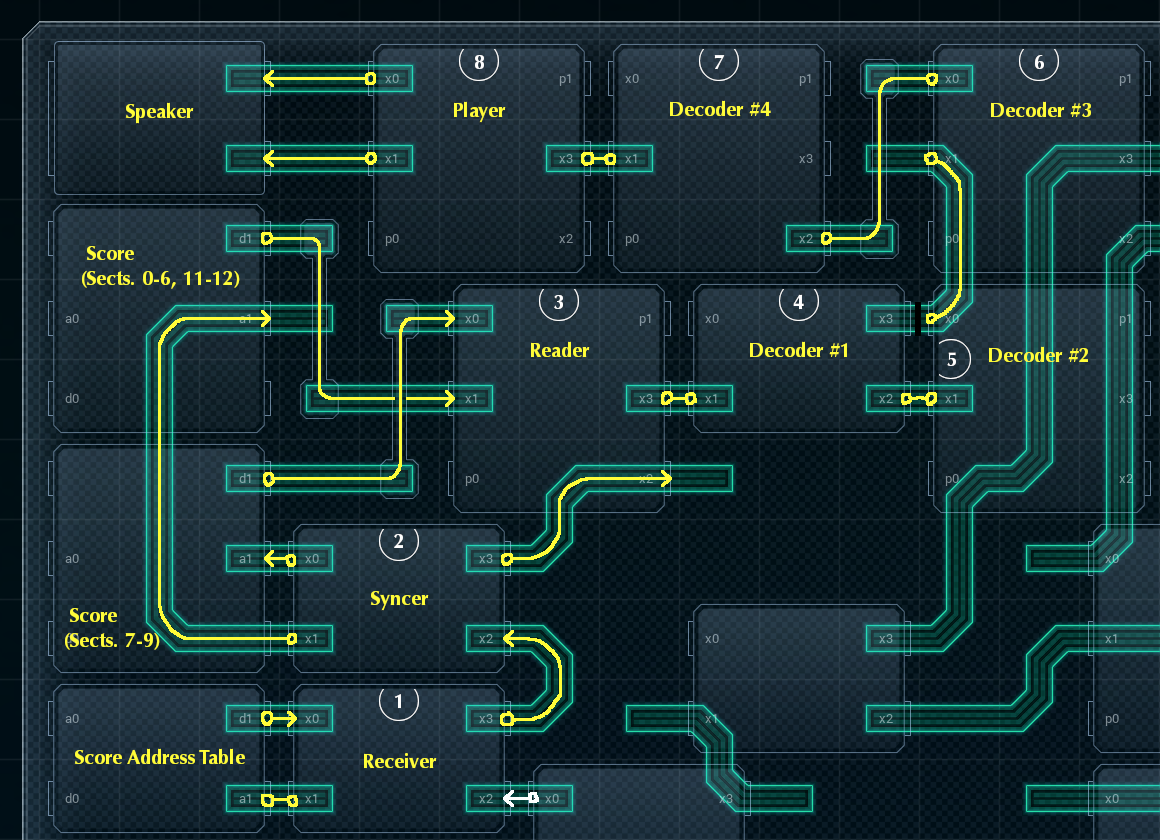
1. Receiver
When a cue comes in from the conductor, the Receiver looks up the associated cell in the Score Address Table, and sends that value (which codes for which score chip to use, and where in the chip to start playing the score) to the Syncer. If the value it read from the table is a -1, it does nothing instead.
2. Syncer
The Syncer takes the value from the Receiver and splits it into two parts. The leftmost digit of the value indicates which Score ROM chip to use: #1 (the upper one) or #2 (the lower one). The other two digits of the value are the address to set the ROM chip to. The Syncer sets the correct ROM chip to the correct address, then passes the number of which chip to use on to the Reader.
3. Reader
The Reader is one of the most complicated MCs in this part, as it is at the center of the part's 'push-pull' timing architecture. It receives input as follows:
A. From the Syncer, the Reader gets notified over XBus (on its x2 line) when a new section is starting. Effectively, cues are 'pushed' out from the conductor end, and find their way to activate the Reader.
B. The Reader is also notified over a different XBus line (x3) when the Player and Decoders, down the chain, are ready for the next note. The Player and Decoders will always send a 'next note' request after the current pattern has finished playing - they don't know what the conductor is doing. They just know that the Reader will always provide new notes on request. Effectively, 'next note' cues are 'pulled' down from the Player end.
This puts the Reader in an impossible position. For each section, it has to receive the wakeup message from the conductor, deliver all the notes to the Player (cued by the Player as necessary), then go back to sleep so that it can receive the message from the conductor again. It can't ignore the conductor's message while it's waiting for a 'next note' message, because then the Syncer will be trying to pass the message on and it'll block. It also can't not respond to a 'next note' request when waiting for the conductor's message, because the Decoders will be reading, and it'll also block.
Before you ask, a read/write block in the simulator's sandbox mode is just like a block in the production mode, except it doesn't pop an error message to show you where the block is - you have to track it down yourself. TODO_EMOTE
What makes this all work is the '0' entries in the Score ROM chips. They signal the Reader that the section is finished, a conductor message will be coming in in this time unit, and that it's safe to wait for it. With this, the bass part hums along like a finely honed watch.
If you're wondering why I made it this way, the answer is simple: variable length note patterns. As mentioned above, note patterns for the bass part can be anywhere from 1 to 5 eighth notes long. There's not enough space in the Reader MC to tell it how long to wait before sending the next cell of the ROM chip, so instead I used this message-driven model; the Player can ask when it's ready for the next pattern. It's fiddly, but it works.
4.-7. Decoders #1-4
Now that we're upstream from the Reader and firmly in the land of 'pull' timing, the design becomes a lot simpler. Each of the Decoders is responsible for decompressing the single ROM cell read and passed on by the Reader, and turning it into a sequence of 'play this note' values to send to the Player.
Each Decoder has the following general pattern:
A. Wait for the timing pulse from upstream (the Player). Pass it on to the next Decoder or the Reader, and wait for a response.
B. When getting a response (the note pattern), transform it in some way. The nature of the transformation varies by Decoder.
C. Send the transformed notes back upstream towards the Player, where they'll pass through the next Decoder.
More specifically, here's what each Decoder does to the note pattern on their way to the player:
4. Decoder #1
If the note pattern is a negative number (signifying an eighth rest after the note pattern is done), this Decoder multiplies the pattern by -1 to turn it into a positive number, and passes it on. It then intercepts the next "next note" pulse to reach it, and replies with 100, code for a rest (00) of 1 eighth note in length.
If the note pattern is a positive number, the Decoder passes it on unaltered.
5. Decoder #2
If the note pattern starts with a 7, indicating two eighth notes in an octave, this Decoder replaces the '7' with a '1' to make it look like a regular single eighth-note play request, and passes the altered pattern on. It then adds 12 (one octave) to the pitch of the eighth note it sent, intercepts the next "next note" pulse, and replies with the pitch-shifted eighth note.
If the note pattern starts with something else, the Decoder passes it on unaltered.
6. Decoder #3
If the note pattern starts with an 8, indicating the pattern of 4 eighth notes with the lower third note, this Decoder replaces an '8' with a '2' to play the first two eighth notes of the pattern, passing the altered pattern on. It then intercepts the next two "next note" pulses, sending the pitch-shifted lower note (subtracting 5 from the pitch value), then the restored fourth note, up to the Player as single eighth notes.
If the note pattern starts with something else, the Decoder passes it on unaltered.
7. Decoder #4
This Decoder transforms every note pattern that passes through it. It splits the pattern into two parts: the first digit (pattern code), and the last two digits (the pitch), and sends them to the Player as two separate values.
This Decoder doesn't intercept "next note" pulses.
Once the dust has settled, the Decoders have turned the note pattern into a sequence of paired values, ready for the Player at last.
8. Player
This MC actually sends the commands to the speaker to play the notes. It starts by sending a "next note" pulse in the direction of the Reader, then storing the pattern code it receives in return into its acc, and the pitch into its dat. It then sends the note to the speaker.
If the pattern code is a '6' (quarter note), it waits 8 time units and clears acc; otherwise, it waits 4 and subtracts 1 from acc. Once the note is done, the player MC stops the note by sending a value of to the 'instrument' pin of the speaker, which stops any notes in progress. If there's any value still left in acc, it sends the note to the speaker and repeats as necessary (this is how the repeated eighth notes are played); otherwise, the Player's script repeats, it sends out another "next note" pulse, and the cycle begins all over again.
The speaker for this part uses instrument #4, "Rubber Bass".
Total cost for this part: 3x MC4000X (¥9) + 5x MC6000 (¥25) + 1x 200P-14 (¥2) + 2x 200P-33 (¥8) + 1x FM/iX (¥5) = ¥49.
Part 2 - Main Harmony Guitar (HARMONY1)
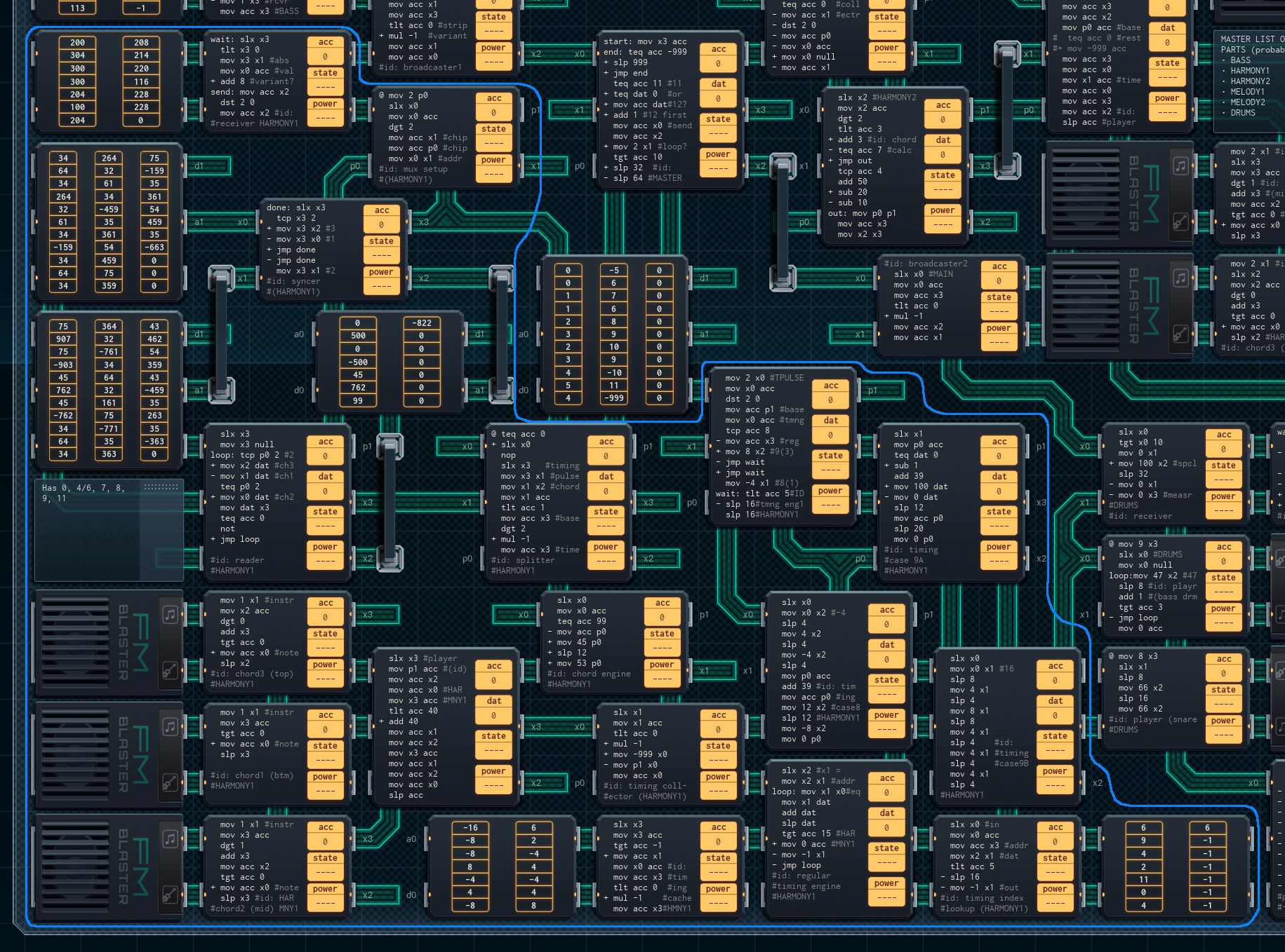
The main harmony guitar was the second part I constructed, the most complicated, and one of the most if not the most difficult part of the whole endeavor. Like the bass part, it stores compressed patterns of notes in its ‘Score' ROM chips, and also uses a push-pull timing architecture because of this (confused? see the explanation for the bass part's "Reader" chip, above). Unlike the bass part, this part plays 3-note chords and not single notes - necessitating extra data storage and decoding.
Harmony Guitar Chord Encoding
Each pattern of harmony guitar notes takes up not one, but two cells in the Score ROM chip. The first cell lists the chord to produce (each digit of the chord cell says how many semitones to put the next note of the chord ahead of the previous one). The first digit of the second cell lists the timing pattern. The last two digits of the second cell list the pitch of the bottom note of the chord.
Different chord patterns produce different chords:
0 = no chord; all speakers will play the same note
32 = minor 3rd with added 4th note (technically a kind of 7th chord)
34 = minor chord
35 = major chord, first inversion*
43 = major chord
45 = minor chord, first inversion
53 = minor chord, second inversion
54 = major chord, second inversion
75 = octave with a 5th in the middle
99 = special cue - two minor chords, going from a first to a second inversion (45 to 53)
*For those who aren't musical: An 'inversion' is when you take the lowest note of a chord and put it on top by raising it an octave. The new chord sounds pretty similar, only higher-pitched. The pitch called for in the score ROM chips is always the note that's on the bottom after the inversion has happened, if one is called for.
On top of that, different first digits in the second cell key for different timing patterns:
0 =

1 =

2 =

3 =

4 =

5 =
 (rest one measure)
6 =
7 =
8 =

9 =

(Timing patterns from 0-4 last for half a measure. Patterns from 5-9 last for a whole measure.)
Finally, if the second cell is negative, it indicates the end of a section, which will cause the Data Splitter to wait for a cue from the conductor before continuing.
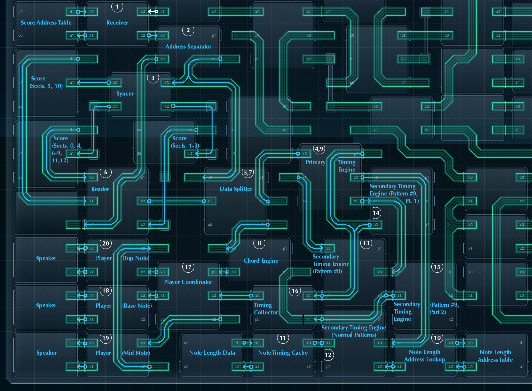
How It All Works
1. Receiver
Like with the bass Receiver chip, the harmony guitar Receiver reads the section number from the broadcaster, pulls the matching cell from the attached Score Address Table, and sends it on. There is one extra wrinkle, though - this Receiver gets the section number twice. The first value received will be a negative number if the section to be used is a variant section, and positive otherwise. The second value is always positive, and this is what gets sent to the Score Address Table's address line.
Once the Receiver has pulled the value from the Score Address Table (which will indicate where and from which ROM chip to start reading the score section), there's one extra wrinkle: if the section is supposed to be a variant, the MC adds 8 to it. This will make the Reader read from the variant section data instead of the normal section data - the variant data is stored right after the normal data. Both of the sections that have variants (#5 and #10, which are the second half of the initial vocals section and the second half of the chorus) are exactly 8 values long when stored, so 'add 8' works in both cases.
Once the Receiver has the address, it sends it off to the Address Separator twice: the first time with the first digit (indicating the chip to send to) intact, the second time with it removed. Both values are used in different places down the line.
2. Address Separator
The next MC in the line, the Address Separator, receives the address with the first digit, removes everything but that first digit, and sends it along its output line (x1) to the Syncer just below it. However, it also sends this same digit along its simple I/O line, p0 (!) to the reader, before sending the last two digits (received from its input) to the Syncer again.
There's a specific reason for all of this.
Put simply, the bass part had two Score ROM chips to choose from, so the bass Syncer (to set the ROM chips' addresses) and the bass Reader (to read from the ROM chips) could both have one XBus line for input, another XBus line for output, and then the remaining two XBus lines would each go to a ROM chip.
The harmony guitar uses the same syncer-reader design pattern, but there are three score chips to read from / set the address of instead of two. So, the harmony guitar Syncer and Reader can only have a single XBus line for communicating with other chips.
This means that the Reader needs a way to know which chip to read from, without using an XBus line (as the XBus line is used to output data)*. So, once the Address Separator sets its simple I/O line, that value sticks and tells the Reader (on the other end of the wire) which chip to read from until the Address Separator changes it.
*OK, so you could have it so that when the Reader is pinged to read the next value, the ping tells it which chip to look at. This way seemed simpler at the time, though.
The output to the Syncer has a side effect as well. The Syncer doesn't have space for an output line (as its other XBus lines are connected to the Score ROM chips), so the pulse that notifies the Syncer also wakes up the Data Splitter (see 5. Data Splitter Part 1, below), getting it ready for a pulse from the Primary Timing Engine. Effectively, the Address Separator's output acts to bridge the two areas of the part: the MCs leading to the Syncer, and the MCs reading from the ROM chips and processing the data (which aren't otherwise directly connected to one another).
3. Syncer
Once the Syncer receives input with a ROM chip number and address, it sets the correct ROM chip's address pointer to the address it received. That's all it does.
4. Primary Timing Engine (Part 1)
The Primary Timing Engine MC, sends out a pulse leftwards to the reader (by way of the data splitter) to cue the reader to read the next measure (or half-measure). (It sends this pulse at the start of each new measure or half-measure, depending on what timing pattern was last read.)
5. Data Splitter (Part 1)
When the Data Splitter (between the Reader and Primary Timing Engine) gets the timing pulse from the Primary Timing Engine, it immediately passes it on to the Reader on its left. However, there's one circumstance where this 'pass' is a bit delayed.
If the harmony guitar part is about to start a new section (that is, at the start of the playback, or after the Data Splitter gets a negative value from the Reader), the Splitter will hold off on processing the timing pulse until it gets a cue from the Address Separator instead (on the Splitter's x0). This is to ensure the Syncer has had time to properly set the address of the ROM chip the Reader is supposed to read from.
6. Reader
When the Reader is cued by a timing pulse on its I/O line (x3), it checks its p0 (set by the Address Separator) to see which ROM chip it should be reading from. Then, it reads two values from the chosen ROM chip, and sends them out on x3 to the Data Splitter.
7. Data Splitter (Part 2)
The fun starts when the Data Splitter gets a pair of values in from the Reader. The Data Splitter, as its name might suggest, sends these values off in different directions.
The first value, which stores the chord information, gets sent to the Chord Engine right below it (see 8. Chord Engine, next). The second value (storing timing and pitch) gets sent along to the Primary Timing engine - twice. The first time, the entire value is sent - this will be used for its pitch value. The second time, only the leftmost digit of the value is (and it's made positive if it's a negative number). This digit will be processed as timing information.
If the second value the Splitter received was a negative number, signaling the end of a section, the Data Splitter will wait for a pulse from the Address Separator before it starts listening to the Primary Timing Engine again.
8. Chord Engine
Once the paired values of the next notes to play leave the Data Splitter, they're sent in two separate directions to be processed separately. The Chord Engine, just below the Data Splitter, gets the chord value.
For the most part, the Chord Engine's job is to pass the chord it receives on to the Player MC to its left. However, if the Chord Engine receives the special code '99', it will instead output '45', wait for 12 time units (the length of three 16th notes), and change its output value to '53' (these two values code for two different minor chords).
It's also worth noting that the Chord Engine outputs its data over simple I/O, not XBus. This is so that the Player can use one chord value for an entire pattern of chords, until a change is called for.
9. Primary Timing Engine (Part 2)
The Data Splitter sends the information on the pitch and timing of the chords back to the Primary Timing Engine, which acts as a decoder. The Primary Timing Engine splits the information and sends it in two directions again!
The pitch value gets copied and sent out on the Primary Timing Engine’s p1 (simple I/O line), which will end up at the Timing Collector below and slightly to the left of it. The timing value (a single digit), however, triggers one of three possible reactions depending on what the number is.
If the timing value is between 0 and 7, the Primary Timing Engine will send the ID number out on its x3, waking up the Note Length Address Lookup MC (which will eventually notify the Secondary Timing Engine for Normal Patterns MC). These MCs will then handle generating the correct timing pattern from storage.
For more about the normal timing patterns, see 10. Note Length Address Lookup, 11. Note Timing Cache, and 12. Secondary Timing Engine for Normal Patterns, all below.
If the timing value is an 8, it refers to this pattern:
In this case, the Primary Timing Engine will send a ping on its x1, to wake up the Secondary Timing Engine MC for Pattern #8 just below it. This MC handles that pattern in software.
For more information about Timing Pattern #8, see 13. Secondary Timing Engine for Pattern #8, below.
Similarly, if the timing value is a 9, it refers to this pattern:
In this case, the Primary Timing Engine sends a ping on its x2, which wakes up both Secondary Timing Engine for Pattern #9 MCs. Yes, that’s right - one timing pattern has two whole MCs devoted to playing it back!
For more information about Timing Pattern #9, see 14-15. Secondary Timing Engine for Pattern #9, Parts 1 and 2, below.
10. Note Length Address Lookup
Most timing patterns will result in the Primary Timing Engine sending the ID number of the pattern to this MC, near the bottom right of the harmony guitar area. The Note Length Address Lookup MC sends the ID it receives to the address line of the attached small ROM chip on its right. That ROM chip - the Note Length Address Table - is an index to the Note Length Data table in the other small ROM chip to the far left.
Once the Note Length Address Lookup MC has the address of the starting location in the Note Length Data table to use, it sends it out to the Note Timing Cache, by way of the Secondary Timing Engine. It will also send a reminder ping to the Note Timing Cache after half a measure if this pattern is supposed to be a full-measure pattern, to keep things going.
11. Note Timing Cache
The Note Timing Cache gets the address of where it’s supposed to start reading from the Note Length Data table ROM chip just to its left. It then reads values from the Note Length Data table for as long as the Secondary Timing Engine for Normal Patterns keeps asking for more data.
The Note Length data table represents the following sequence of notes:
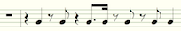
The Secondary Timing Engine (cued by the Note Length Address Lookup MC) will ask for either 2 or 4 quarter notes’ worth of time from this sequence, starting wherever in the sequence the Note Length Address Lookup MC says it should start. Each of the timing patterns from 0-7 are subsequences of this sequence.
The Secondary Timing Engine reads each read value twice, so the Timing Cache outputs the value twice - making the second copy of the value positive if it’s originally a negative value (negative values indicate rests in the Note Length Data chip).
12. Secondary Timing Engine for Normal Patterns
This MC passes messages between the Note Length Address Lookup MC and the Note Timing Cache. It reads the resulting data the Timing Cache outputs, passing it on to the Timing Collector (see 16., Timing Collector, below). It also keeps track of the sum of the absolute value of the note timing values it’s received - if the sum adds up to 16, the Secondary Timing Engine will stop, as it’s read half a measure worth of time. (If the timing pattern it’s receiving is supposed to be a full-measure pattern, the Note Length Address Lookup MC will ping the Secondary Timing Engine to get it to keep going and receive the second half of the measure from the Timing Cache.)
13. Secondary Timing Engine for Pattern #8
This MC, sandwiched vertically between the normal Secondary Timing Engine and the Primary Timing Engine, is responsible for outputting Timing Pattern #8:
This pattern is used just after the intro section of the piece.
One of the reasons this pattern is being output manually is that the second note is actually one semitone lower than the first. When the time comes to do the changeover, the Secondary Timing Engine for #8 takes the note pitch value from p0, adds 39 to it, and puts it back out on p0, overwriting the previous value.
This works for two reasons: First off, if two MCs write different values to a simple I/O wire, the highest value wins. Second - the entire part is set up deliberately to allow this override. The pitch values of cells in the Score ROM chips that use the 8 and 9 timing pattern codes have had 40 pre-subtracted from them. The harmony guitar Player knows that if a note has a pitch of below 40, it should have 40 added to the pitch before playing it. When this Secondary Timing Engine adds 39 to the pitch value, this is the same as adding 40 by itself— and then subtracting 1! Effectively, this Secondary Timing Engine is overriding the pitch put out by the Primary Timing Engine… with simple I/O lines - ensuring that it has the highest simple I/O value, but it’s read as a lower note than what came before it.
Aside from this wrinkle, the code for this Secondary Timing Engine is pretty simple, sending the pattern of notes and rests shown above to the Timing Collector (see #16 below.)
14-15. Secondary Timing Engine for Pattern #9 (Parts 1 and 2)
Timing Pattern #9, used only in the intro to the piece, presents a similar challenge to timing pattern #8: it has notes in a nonstandard rhythmic pattern, and a step down in the middle:
However, this time, there are enough notes that the pattern is split into two MCs, both on the right side.
The Part 1 MC concerns itself solely with the pitch of the notes. It uses the same 'add 39' trick that the Secondary Timing Engine for Pattern #8 does (see just above) to override the pitch set by the Primary Timing Engine in the middle of the measure. It sends the updated pitches, on its p0 line, to the Timing Collector.
(There’s one extra extra wrinkle: the second time this MC is called on to do this, the extra ‘sub 1’ instruction kicks in, lowering the pitch by two semitones instead of one. This is to deal with the intro’s chord progression harmoniously.)
The Part 2 MC focuses on the actual notes and rests used in the timing pattern, and sends those timing values to the Timing Collector in the correct rhythm.
16. Timing Collector
The Timing Collector, in the center bottom of the harmony guitar part, is where just about everything comes together. This MC takes input from all three Secondary Timing Engines and the Primary Timing Engine.
The Timing Collector’s actual job is simple: when it receives an XBus pulse from a Secondary Timing Engine (on its x1 line), it checks if the pulse is positive (a note) or negative (a rest). If it’s positive, it sends the pitch value (received from one of the Timing Engines on its p1) to the Player Coordinator, to its left, followed by the pulse as a timing value for how long the next note should be. If it’s negative, the Collector sends -999 in place of the pitch (to indicate “silence”), turns the timing value into a positive number, and sends it along.
17. Player Coordinator
The Player Coordinator exists for one simple reason: the harmony guitar part has to play chords. Instead of one Player MC to deal with, there’s three - one for each note of the chord. When woken up by the Timing Collector, the Player Coordinator handles this by taking the chord value from the Chord Engine, and sending it to both the ‘Mid Note’ and ‘Top Note’ Players (the Base Note Player doesn’t use it). From there, it sends the pitch value (from the Timing Collector) to the ‘Base Note’ and ‘Mid Note’ players (the ‘Mid Note’ player will pass it on to the ‘Top Note’ player - this saves a line of code), and sends the timing value of the note to all three. Then, it waits for the next note from the Timing Collector.
(The ‘add 40’ line is so that special timing patterns can work properly. See 13. Secondary Timing Engine for Pattern #8, above, for more info.)
18-20. Players (Base, Mid, and Top Note)
The Player MCs are mostly the same, but with some slight differences. In order to replicate the three notes of a chord, the Players all take the same pitch value and play it for the same amount of time - but the Mid Note and High Note Players raise their pitch by one of the digits of the chord value they received first. Here’s how each player works, step by step:
A. The Mid Note and High Note Players both get the chord value from the Player Coordinator. They each store one of the two digits of the value in their acc.
B. The Base Note and Mid Note Players both get the pitch value from the Player Coordinator. The Base Note Player doesn’t need to do anything with it, so it just stores it in its acc. Meanwhile, the Mid Note Player adds the pitch value to the stored digit of the chord value, raising the note by several steps.
C. The Mid Note Player passes its boosted pitch value to the High Note Player, which boosts it again by adding it to its own stored chord value digit. All three Players now have pitch values corresponding to the bottom, middle, and top nodes of the chord.
D. All three Players pass their pitch value to their attached speaker. (If the note is less than 0, indicating a rest, this step gets skipped.)
E. All three Players receive the timing value from the Player Coordinator, and wait that long before stopping the note and listening for the next data. The cycle begins again.
The speakers for this part use instrument #1, “Plucktar”.
Total cost for this part: 3x MC4000 (¥9) + 7x MC4000X (¥21) + 8x MC6000 (¥40) + 4x 200P-14 (¥8) + 2x 200P-33 (¥8) + 3x FM/iX (¥15) = ¥101.